Remeha Gas HP 35 A
(LT/HT)
38
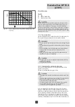
7.5.3 Connecting the CAN-bus to the GEP connectors -
several skids
7KHODVWKHDWSXPSRQHDFKVNLGLVFRQ¿JXUHGDVDQHQGQRGH
in the factory and is ready to be connected with a CAN-bus
cable to the next skid (
see Fig. 29 and Fig. 30
).
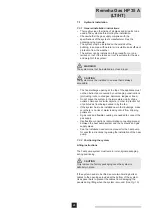
Legend
A
CAN-bus cable casing
B
CAN-bus cable casing cap
D
Skid support beam
E
Last heat pump of the skid
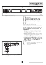
7KHODVWKHDWSXPSRQWKH¿UVWVNLGPXVWEHFRQQHFWHGWRWKH
GEP for the next skid and is changed from an end node (see A
in Fig. 30) to an intermediate node (see B in Fig. 30). Proceed
as follows:
Remove the front casing and open the electrical panel for
WKHODVWKHDWSXPSRQWKH¿UVWVNLG
Under the heat pump, behind the support beam (see E in
)LJ\RXZLOO¿QGWKH&$1EXVFDEOHFDVLQJZLWKFDS
(see A and B in Fig. 29).
Cut off a piece of CAN-bus cable that is long enough for the
connection without any loops forming.
Open the cap of the cable casing and secure the CAN-bus
cable to the puller wire located under the cap.
Use the puller wire to pull the CAN-bus cable through until
at least 50-60 cm protrudes above the other end of the
cable casing.
Remove the puller wire and secure the CAN-bus cable to
WKHFRQWUROXQLWDVGHVFULEHGLQ6HFWLRQ&RQQHFWLQJ
WKH&$1EXVWRWKH*$6+3SXPS
Connect the other end of the CAN-bus cable to the GEP of
WKHQH[WVNLGDVGHVFULEHGLQWKHVHFWLRQ&RQQHFWLQJWKH
&$1EXVWRWKH*(3FRQQHFWRUVVLQJOHVNLG
If there are more than two skids, repeat the procedure until
all the skids are connected.
&ORVHWKHHOHFWULFDOSDQHODQGUH¿WWKHIURQWFDVLQJIRUWKH
heat pump.
T003996-A
E
B
A
D
Fig. 29
CAN-bus cable casing and puller wire
T003994-C
GND
L
H
Jumper J1
GND L
H
P8
P8
S61
S61
A
B
Jumper J1
Fig. 30
CAN-bus cable connection (end node and
intermediate node) on the printed circuit board of the
Gas HP heat pump


