18
Remeha
Gas 3002 ECO
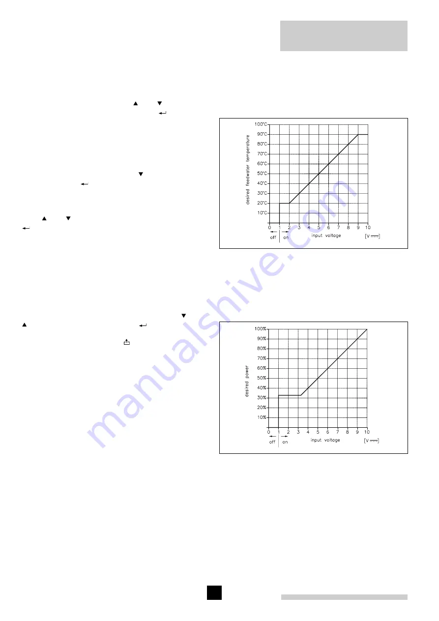
the control will convert the vol ta ge into the required flow
temperature, higher than the measured flow temperature.
At the user level, it is possible to set the maximum
operating temperature. The set point will be limited to this
level, irrespective of whether the analog input calls for a
higher temperature.
B.2 External control
The required power is 0% at 0V and 100% at 10V
(see figure 13). As soon as the voltage exceeds 1V,
the boiler will switch on. As soon as the voltage falls
below 0,5V the boiler will switch off. The maximum
operating temperature can be set at the user level.
C. Computer
C.1 Internal control
The boiler can also be controlled using a computer,
modem or GBS system. The switch-on command and
the required flow temperature is passed on to the
boiler via the RS 232 connection. All values, settings,
etc. can now also be read via the RS 232 connection.
C.2 External control
In this structure, the switch-on and switch-off commands
and the required power are transmitted via the RS 232
connection. Here too, all measurement values and set
tings can be passed on through this connection.
7.3.3 Service level
To prevent unwanted settings by non-experts the service
level can only be accessed after entering a security code.
The security code for this level is 0012.
After entering this code using the ' ' and ' ' buttons in
menu 5 and confirming it by pressing the '
' button, the
service level is accessed.
Now, a selection can be made from 4 options:
1) Service settings
2) Service test
3) History data
4) Service level
II
(factory level).
Select the desired option using the ' ' button and confirm
it by pressing the '
' button.
To 1) Service settings
Various settings can now be made (select desired option
using ' ' and ' ' button and confirm it by pressing the
'
' button.
Option 1: Input selection
Offers the posibility of an internal PI-regulation, by which
the boiler regulates its output based on flow temperature
and the possibility of an external PI-regulation, by which
the boiler output is regulated by means of an external
regulation.
The selection of the options can be obtained by placing
the cursor onto the chosen line by means of the ' ' and
' ' buttons and by pushing next the '
' button. The
choice is confirmed by the two arrow heads which appear
on the selected line. Using the ' ' key, you switch to the
next screen, where it is possible to select the method
according to which the required temperature or required
power can be passed on to the boiler control. There are
three possibilities:
A. Contacts
A.1 Internal control
Via a potential-free contact, the boiler receives a heat
demand command. At the user level, the required flow
temperature can be set. The boiler now will modulate
on base of this temperature.
A.2 External control
Via two potential-free contacts, the boiler can be
switched to minimum or maxi mum power. At the user
level, the maxi mum flow temperature can be set.
B. Analog
B.1 Internal control
The required flow temperature is passed on to the
boiler control via a 0-10V analog signal. As standard,
this signal is set to a temperature of 0°C at 0V and
100°C at 10V (see figure 12), but via the two following
screens it is possible to allocate different values to
the tarting and finishing points, depen ding on the type
of control used. At 0V, a temperature of between -50°C
and +50°C can be selected, and at 10V, a temperature
of b50°C and +300°C. Via a linear line,
Fig. 13 External boiler control by analog (0-10 V) signal.
Fig. 12 Internal boiler control by analog (0-10 Volt) signal.


