8
COMMISSIONING
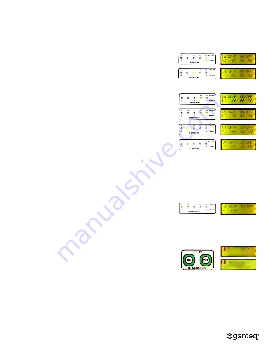
Operate the system in all modes of operation to confirm the thermostat wiring energizes the proper demand on the user interface
and adjust the airflow values and on/off delay values if needed. The values shown on the display screens below, for each thermostat
demand, represent the user interface factory default settings.
Confirm the thermostat wiring provides proper demand to the user interface (UI).
Single stage systems
–
A thermostat demand for heat
should turn on the (W) LED thermostat indicator
on the UI. The display screen on the UI should display (W2), the airflow value and
the on/off delay values.
–
A thermostat demand for cool (or heat pump)
should turn on the (Y) LED
thermostat indicator on the UI. The display screen on the UI should display (Y2), the
airflow value and the on/off delay values.
Two stage systems
–
A thermostat demand for 1st stage heat
should turn on the (W1) LED
thermostat indicator on the UI. The display screen on the UI should display (W1),
the airflow value and the on/off delay values.
–
A thermostat demand for 2nd stage heat
should turn on the (W2) LED
thermostat indicator on the UI. The display screen on the UI should display (W2),
the airflow value and the on/off delay values.
–
A thermostat demand for 1st stage cool (or heat pump)
should turn on the (Y1)
LED thermostat indicator on the UI. The display screen on the UI should display
(Y1), the airflow value and the on/off delay values.
–
A thermostat demand for 2nd stage cool (or heat pump)
should turn on the (Y2)
LED thermostat indicator on the UI. The display screen on the UI should display
(Y2), the airflow value and the on/off delay values.
Continuous Fan Thermostat Demand
–
A thermostat demand for continuous fan should turn on the (G) LED thermostat
indicator on the UI. The display screen on the UI should display (G) and the airflow
value. There are no on/off delay value options for this demand.
User Interface Lockout
–
If the user interface buttons do not function, it may be locked out. The user
interface will automatically lock out after 15 minutes of inactivity.
o
To unlock the user interface
functions, press both DELAY buttons (ON and
OFF) at the same time for 10 seconds. When the indicator changes from “L” to
“U”, release the DELAY buttons; the user interface is now unlocked.
o
Unlocked
is indicated by the “U”,
Locked
is indicated by the “L”..
o
The flashing dollar sign ($) next to the U or L is simply a heartbeat, that
means the control is operating properly.
NOTE:
The UI is set by default to automatically switch from W1 to W2 airflow and Y1 to Y2 airflow 10 minutes after the thermostat
demand for W1 or Y1 is received. This delay setting is to accommodate two stage systems with single stage thermostats.
–
For two stage systems with two stage thermostats, changing this delay value to (0) will more accurately match the HVAC system
demand to the UI operation of the motor.
–
This delay can be adjusted in the OPTIONS menu. See page 12-13 for more details.
©2019, 2020 Regal Beloit Corporation, All Rights Reserved. MCIM20008E • Form# G0075E


