


22
UP 0, UP 1, UP 2, UP 2.4, UP 2.5
4. Adjustment
Attention!
See chapter 1.2
If it is necessary to connect the supply voltage to Electric actuator, make sure by following the
mentioned procedure that there is no injury caused by the electric current. Otherwise,
disconnect the Electric actuator from the electricity network.
Observe safety regulations!
After mechanical connection, electrical connection and checking of connection and function start setting and
adjustment of the device. The adjustment is performed with the EA mechanically and electrically connected and
the connection and functions were checked. The chapter describes the adjustment of the EA to the parameters
given in the nameplate in case that any of its parts is out of tune. The adjusting parts on Fig.1.
Definition of the direction of movement:
•
movement direction "
close
" - the output shaft of the actuator rotates in the clockwise direction when looking
into the actuator control part from the top.
4.1 Adjustment of the torque unit
The switching - off torque are adjusted by the producer for both directions, i.e. for the direction “opening”
(the torque switch S1) as well as for the direction “closing” (the torque switch S2) to the specified value with
tolerance of
±
10%. If not stated else they are adjusted to the maximum rate.
It is impossible to align and adjust the torque unit for EA
UP 0
actuator to alternative values of torque without
test equipment to measure torque.
Adjustment and setting of the torque unit for EA
UP 1
actuator to alternative torque values is possible through
the use of adjustment screws according to
Fig. 2
. Switching-off torque can be reduced by rotating the graduated
screws along the gauge mark on the arm of the torque unit. Adjustment to longest mark results in resetting the
switching-off torque to maximum value. Adjustment to the shortest mark results in the reduction of the switching-
off torque.
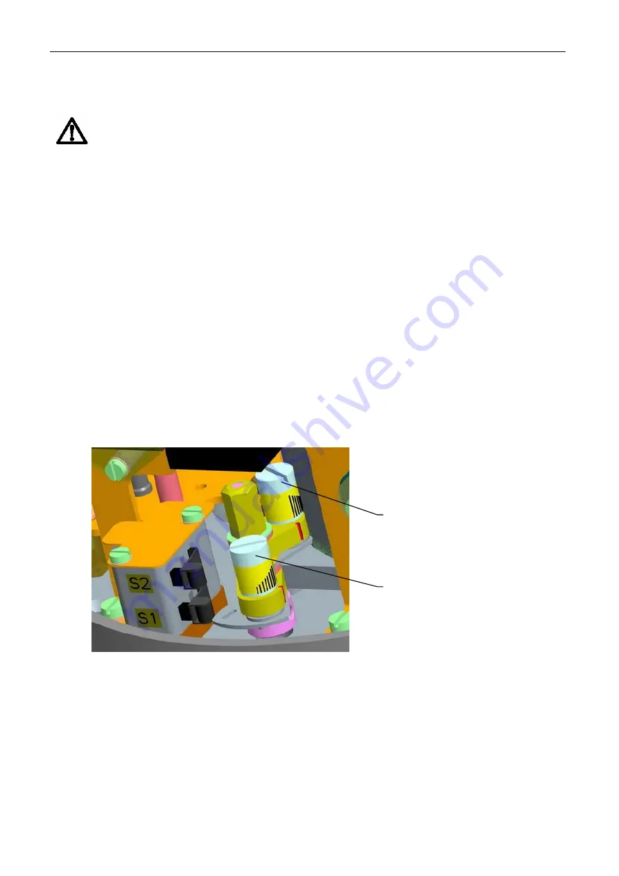
Fig.2
REGULATING
SCREW OF
TORQUE SWITCH
S2
REGULATING
SCREW OF
TORQUE SWITCH
S1
Содержание UP 0
Страница 10: ...8 UP 0 UP 1 UP 2 UP 2 4 UP 2 5 5 9 Fig 1a Fig 1b ...
Страница 11: ...UP 0 UP 1 UP 2 UP 2 4 UP 2 5 9 Fig 1c UP 2 5 with controller ...
Страница 42: ...40 UP 0 UP 1 UP 2 UP 2 4 UP 2 5 7 Enclosures 7 1 Wiring diagrams UP 1 UP 2 UP 2 4 UP 2 5 ...
Страница 43: ...UP 0 UP 1 UP 2 UP 2 4 UP 2 5 41 ...
Страница 44: ...42 UP 0 UP 1 UP 2 UP 2 4 UP 2 5 Wiring diagrams UP 0 ...
Страница 47: ...UP 0 UP 1 UP 2 UP 2 4 UP 2 5 45 7 4 Dimensional drawings Electric part turn actuators Unimact UP 0 UP 1 UP 2 ...
Страница 48: ...46 UP 0 UP 1 UP 2 UP 2 4 UP 2 5 Electric part turn actuators Unimact UP 0 UP 1 UP version stand and lever ...
Страница 49: ...UP 0 UP 1 UP 2 UP 2 4 UP 2 5 47 Electric part turn actuators Unimact UP 1 UP 2 version with local control ...
Страница 51: ...UP 0 UP 1 UP 2 UP 2 4 UP 2 5 49 Electric part turn actuators Unimact UP 2 4 UP 2 5 ...
Страница 52: ...50 UP 0 UP 1 UP 2 UP 2 4 UP 2 5 Electric part turn actuators Unimact UP 2 4 UP 2 5 version stand and lever ...
Страница 53: ...UP 0 UP 1 UP 2 UP 2 4 UP 2 5 51 Electric part turn actuators Unimact UP 2 4 UP 2 5 version with local control ...