


18
ST 0, STR 0
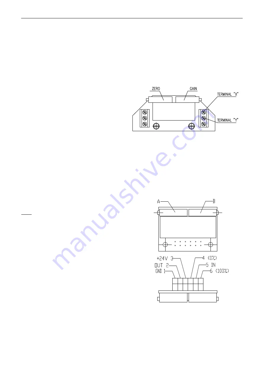
Fig.8
•
Having the transmitter adjusted put the jumper again on the terminals 81 and 82 in case that the
output signal wont be used (the circuit through the terminals 81 and 82 should be closed).
•
Connect the control signal to the terminals 86/87 and 88.
3.4.1 EPV – 3-wire version (Fig. 8, 8a)
The resistive transmitter with the converter is in the plant adjusted to have the output current
signal metered on the terminals 81-82 as follows:
•
in the position ”open“ ............. 20 mA, resp. 5 mA, resp. 10V
•
in the position ”closed“ ........... 0 mA, resp.
4mA, resp.0 mA
according to the specified version of the
converter.
If the transmitter requires a new adjustment
follow these steps:
•
Put the actuator to the position „closed“ and
switch the power supply off.
•
Adjust the resistive transmitter according to
the previous chapter. The resistance is to
be metered on the terminals X-Y, resp. 0%-
100% (Fig. 8, 8a). The used transmitter
resistance is
2000
Ω
resp. 100
Ω
.
•
Switch the converter
′
s power supply on.
•
Turn the adjusting trimmer ZERO resp A to adjust the output current signal rate measured on the
terminals 81-82 to 0 mA, resp. 4mA, resp. 0V.
•
Set the actuator to the position ”open“.
•
Turn the adjusting trimmer GAIN resp. B to adjust the output current signal rate measured on the
terminals 81-82 to 20mA, resp. 5 mA, resp. 10V.
•
Check the output signal of the converter in the both
limit positions, and repeat the procedure if needed.
Note:
The output signal of (0-20mA, 4-20mA, 0-5mA, resp. 0-10V
according to the specification) can be adjusted at the range from
85 up to 100% of the rated stroke stated on the actuator
′
s
nameplate. At values less than 85% the value of the output
signal is reduced proportionally.
3.5 Adjustment of position controller (Fig. 9)
The built-in position controller REGADA of new
generation is a user-friendly control system to control
actuators with an analogue signal. The controller takes
advantages of high-power RISC processor MICROCHIP to
perform all functions. It provides also continuous
automotive diagnostics of the system, error messages as
well as number of relay switching and number of
controller's operation hours. Placing an analogue signal
onto the input terminals of the terminal board 86/87 (GND,
-) and 88 (+) causes that the EA output is reset.
Required parameters and functions can be programmed using function buttons SW1 - SW2 and
LED diodes D3 - D4 placed directly on the controller, see Table 2.
Fig. 8a
Содержание ST 0
Страница 1: ...74 0813 02 INSTALLATION SERVICE AND MAINTENANCE INSTRUCTIONS Electric linear actuators ST 0 STR 0...
Страница 26: ...24 ST 0 STR 0 6 Enclosures 6 1 Wiring diagrams Wiring diagrams for EA ST...
Страница 29: ...ST 0 STR 0 27 Flange DIN 3358...
Страница 30: ...28 ST 0 STR 0 Pillars...
Страница 31: ...ST 0 STR 0 29 Flange...
Страница 32: ...30 ST 0 STR 0 Flange...
Страница 33: ...ST 0 STR 0 31 Flange...
Страница 34: ...32 ST 0 STR 0 Pillars...
Страница 35: ...ST 0 STR 0 33 Flange...
Страница 36: ...34 ST 0 STR 0 Pillars...
Страница 37: ...ST 0 STR 0 35 Flange...
Страница 38: ...36 ST 0 STR 0 Flange...
Страница 39: ...ST 0 STR 0 37...
Страница 40: ...38 ST 0 STR 0...


