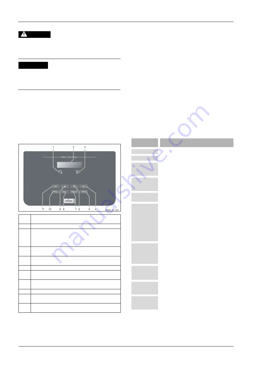
Controller
12
—
English
Fillcontrol Auto
—
22.09.2020 - Rev. C
8.1.5
Restarting
CAUTION
Risk of injury due to pump start-up
Hand injuries may occur when the pump starts up if you turn the pump
motor at the impeller using a screwdriver.
•
Switch the pump to a zero-volts state before turning the pump at the
fan wheel with a screwdriver.
ATTENTION
Device damage due to pump start-up
Pump damage may occur when the pump starts up if you turn the pump
motor at the impeller using a screwdriver.
•
Switch the pump to a zero-volts state before turning the pump at the
fan wheel with a screwdriver.
After an extended standstill time (the device is de-energised or in Stop mode),
the "PU" pump may jam.
•
Use a screwdriver to rotate the pump at the fan wheel of the pump motor
before restarting.
Note!
A jamming of the "PU" pump is prevented during automatic operation
thanks to forced starting action (after 24 hours).
9
Controller
9.1
Operator panel
1
Error LED
•
The Error LED illuminates in the event of a fault
2
Display
3
Auto LED
•
The Auto LED illuminates green in Automatic mode
•
The Auto LED flashes green in Manual mode
•
The Auto LED is not illuminated when the system is stopped
4
OK
•
Confirm actions
5
Stop
•
For commissioning and entry of new values in the controller
6
"Back" to the previous menu
7
Manual
•
For tests and maintenance tasks
8
Auto
•
For continuous operation
9
"Forward" to the next menu
10
Menu
•
Call up the Customer menu
11
Quit
•
Acknowledge messages
Selecting and changing parameters
1.
Use "OK" (5) to select the parameter.
2.
Use the "
▼
" (7) or "
▲
" (9) arrow keys to change the parameter.
3.
Use "OK" (5) to confirm the parameter.
4.
Use the "
▼
" (7) or "
▲
" (9) arrow keys to switch to a different menu
option.
5.
Use "Quit" (11) to switch to a different menu level.
9.2
Configuring settings in the controller
System-specific values can be corrected via the customer menu. In the course of
initial commissioning, the factory settings must first be adjusted for the system-
specific conditions.
Note!
For a description of the operation, see chapter 9.1 "Operator panel" on
page 12 .
All grey marked menu items must be reviewed during commissioning.
Press "Manual" to switch to manual operation.
Press "Menu" to display the first main menu option "Customer menu".
To navigate and set the values:
•
Use the "
▼▲
" arrow keys to navigate and set the values in the selected
main menu.
•
Press "OK" to open the next sub-menu.
•
Press "OK" to confirm the changed setting in the sub-menu.
Indication on the
display
Meaning
Customer menu
Switch to the next main menu option.
Language
Standard software in various languages.
Time:
Adjust the "Hour", "Minute", and "Second" display when
each begins to flash.
This time is used for entries in the fault memory.
Date:
Adjust the "Day", "Month", and "Year" display when each
begins to flash.
This date is used for entries in the fault memory.
Fillcontrol /
Magcontrol
Select between the make-up variants "Levelcontrol" and
"Magcontrol".
Min.op.pressure
01.8 bar
The system displays the "Minimum working pressure"
message when you have set the "Magcontrol" make-up
variant. Enter the value for the minimum operating
pressure.
Note!
Calculation of minimum operating pressure, see
chapter 7.2 "Determining the P
operating pressure for the controller" on page 9
.
Safety valve
pressure
The system displays the "Safety valve pressure" message
when you have set the "Magcontrol" make-up variant.
Specify the tripping pressure of the applicable safety
valve for the device protection. This is usually the safety
valve at the system heat generator.
Make-up
Switch to the "Make-up" sub-menu.
•
Press "OK" to open the menu.
•
Use the "
▼▲
" buttons to open the sub-menu.
Max. make-up time
010 min.
Pre-selected time for a make-up cycle. Upon expiry of
this set time, the system interrupts the make-up and
returns the "Make-up time" fault message.
Max. make-up
cycles
003 / 2 h
If the set number of make-up cycles is exceeded within
two hours, the system interrupts the make-up and
returns the "Make-up cycles" fault message.


