See last page for copyright and document info, File: Reeve_GpsNtp-Pi_Setup.doc, Page 4
Antenna: An outdoor external antenna is recommended but initial setup and testing can be performed indoors.
For testing, the antenna should be placed on or near a window, preferably a south-facing window. If the Adafruit
Hat is used with its internal patch antenna, the RPi assembly should be placed near a window or on a windowsill.
The antenna must have a clear view of the sky. Generally, GPS performance is higher if it is installed to minimize
multipath interference caused by reflections from rooftops and walls. The internal patch antenna and external
antennas that may be purchased with the Adafruit and HAB Supplies GPS receivers are far from optimum for
timing applications because of their irregular gain patterns and nonexistent multipath suppression capabilities.
On the other hand, they are cheap and adequate for amateur radio astronomy applications.
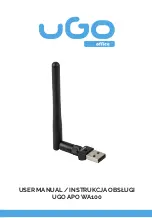
The HAB Supplies antenna is shown in the image on
the left side and the optional Adafruit antenna is
shown right. Antenna dimensions are approximately
50 x 35 x 15 mm. Both antennas have a magnetic base
for mounting to a ferromagnetic surface but neither is
rated for outdoor service. Both are patch antennas
with small coaxial cables and SMA-M connectors.
Their manufacturers and specifications are not given
by the vendors.
If a different antenna is contemplated, the following guide may be used to select it:
Polarization: Right-hand circular
Mode: Active
Impedance: 50 ohm
Voltage: 3.0 to 3.6 Vdc (supplied by receiver)
Current: < 20 mA at 3.3 Vdc (the GTop receiver current limits the antenna bias-tee to 28 mA at 3.3 V)
Gain: 15 to 50 dBi
Noise figure: < 1.5 dB
Connecting an external antenna: If an external antenna is to be connected to the Adafruit GPS receiver board,
use a 150± mm long flexible jumper between the onboard U.FL-M connector and the SMA-M antenna cable
connector (a jumper is available from Adafruit). The flexible jumper is necessary so that no significant force is
placed on the onboard connector during operation. If the optional antenna from HAB Supplies is used with their
GPS board, there is no need for a flexible jumper (the supplied antenna has RG-174 coaxial cable, already quite
small and flexible).
Network: Connect a high-quality Cat5 network cable between the RPi LAN connector and a LAN switch or router.
The wired connection is used for provisioning. A WLAN connection can be installed later.
Power Supply: Before connecting a 5 V power supply, read this first: DO NOT attempt to power GpsNtp-Pi using
a USB port on a desktop or laptop PC or handheld device. Power measurements of GpsNtp-Pi on the RPi model
B+ showed < 1.5 W average dc load. However, when the RPi is booting and depending on connected peripherals,
the measured load current can be > 670 mA (3.4 W), too high for a PC USB port.
Содержание GpsNtp-Pi
Страница 1: ...GpsNtp Pi Installation and Operation Guide See last page for copyright and document information...
Страница 8: ...See last page for copyright and document info File Reeve_GpsNtp Pi_Setup doc Page 6...
Страница 29: ...See last page for copyright and document info File Reeve_GpsNtp Pi_Setup doc Page 27...


