59
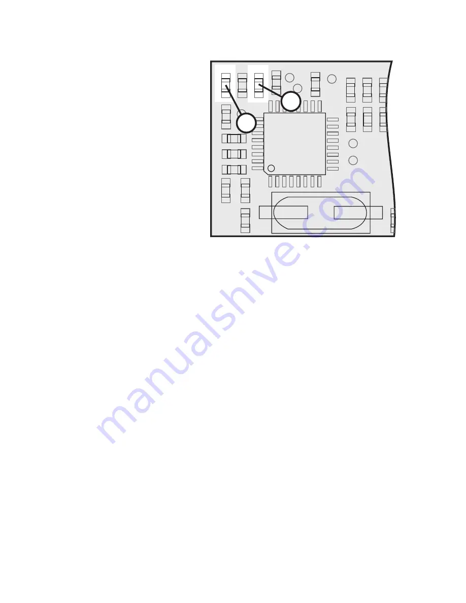
g) LED Status Display
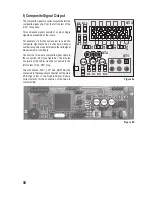
The composite signal converter has a green and a
red LED for status display.
A green LED („LED1“) indicates that the electronics
are in normal operation. This means that servo
signals can be measured, and if required a
composite signal can be generated. When the
greed LED goes out, there is a basic interference
in the electronics.
A red LED („LED2“) shows that no servo signals
are present. The reasons fort his may be reception
interference, lack of power supply to the receiver ,
switched-off transmitter of contact errors in the
connection lines.
Behaviour in case of reception interferences
The composite signal converter measures the signal quality and thus also recognises reception interferences. Since
channels 1 - 4 are mainly used for general control of models, they are specifically described.
Interferences on channels 1 - 4
For these channels, verification of a valid pulse width (between 1 and 2 ms) is performed. If an error is recognised, the
composite signal is generated with the last valid value. When the error rate exceeds the measure for proper reception,
the composite signal converter does not output any composite signal anymore and activates the red LED. Now the
reception problem can be recognised by the downstream logic and no reception problems are concealed. If the input
signal is valid again, the red LED goes out and a composite signal is generated.
Interferences on channels 5 - 8
If the reception interference only acts on channels 5 - 8, a composite signal continues to be generated for channels
1 - 4 and channels 5 - 8 are output with an invalid pulse length. Thus, it is possible to continue to control the model, but
the interference can be recognised by a downstream logic at channels 5 - 8. When the input signal is valid again, a
regular composite signal is output.
R18
R17
R21
R20
R19
C2
C3
C4
C5
LED1
LED2
C
R6
R5 R1 R9
R2 R10
Q1
U1
TP4
TP3
TP8
TP2
TP1
TP7
C7
Rot
LED1
Rot
LED2
Figure 9
Содержание 450 ARF QC09
Страница 166: ...166 ...
Страница 167: ...167 ...


