reedinstruments
www
com
13
Diode Test
WaRninG: To avoid electric shock, do not test any diode that has
voltage on it.
1. Insert the black test lead into the negative COM terminal and the red
test lead into the positive Diode terminal.
2. Set the function switch to the diode/continuity
position.
3. Make sure all the power is off.
4. To select the diode test measurement mode, press the MODE button
until the (diode/buzzer)
symbol appears in the display on the left
hand side. Pressing the MODE button again will switch the measure
-
ment mode to continuity test.
5.
Connect the test leads to the diode being measured. When measuring the
forward voltage across diode, a normal diode will indicate 0.4V to 0.7V
and the reverse voltage will indicate “OL” (same as on open condition).
For a short-circuited diode, a value near 0 mV will be displayed.
Capacitance Measurement
WaRninG: To avoid electric shock, discharge the capacitor under
test before measuring.
1. Insert the black test lead into the negative COM terminal and the red
test lead into the positive CAP terminal. The polarity of the lead con
-
nection is positive “+”.
2. Set the function switch to the CAP position.
3. Connect the test leads across the capacitor being measured and be
sure that the polarity of the connection is respected.
Notes:
• When checking in-circuit capacitance, be sure that the circuit’s power
has beened turned off and that all capacitors are fully discharged.
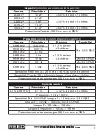
• In capacitance measurement mode the range control mode is auto-ranging.


