REDLAKE MASD, INC.
4. Data Record Input 0; Data Record Input 1. Each Data Record input controls a marker on the
video image. These inputs must be TTL signals; when the signal is +5 volts, the marker is
white, and when the signal goes low (0 Volts), the marker goes black. These signal levels
may be changed independently at any time during Record to identify a specific frame.
5. Strobe Out. This is a TTL output pulse, normally low that goes to +5 volts to indicate a frame
exposure. The length of the pulse is synchronized to the shutter setting.
3.4 The
Motion
Scope
PCI Controller Board
Warning!
The Controller board is FRAGILE. Handle with caution to avoid bending or flexing board.
This PCI Controller board plugs into a PCI connector on the Main Board, and contains all control
and image digitizing functions for the system. There are eight switches on the rear plate
referenced S1 through S8. Switches S1 to S6 are factory set and must not be changed. Switch 7
enables the Data Record function when set to the RIGHT. S8 selects NTSC (LEFT) or PAL
(RIGHT) for the “Composite Out” connection to a remote monitor or VCR.
3.5 The
Motion
Scope
Control Functions
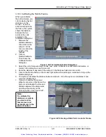
All controls, status and setup values are shown in the application window. The video pictures are
shown in camera windows or computer file windows. The system has five principle functions: Live,
Record, Save, Load and Playback.
3.5.1 The Initial Application Window
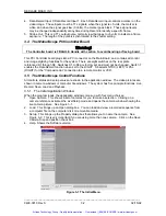
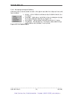
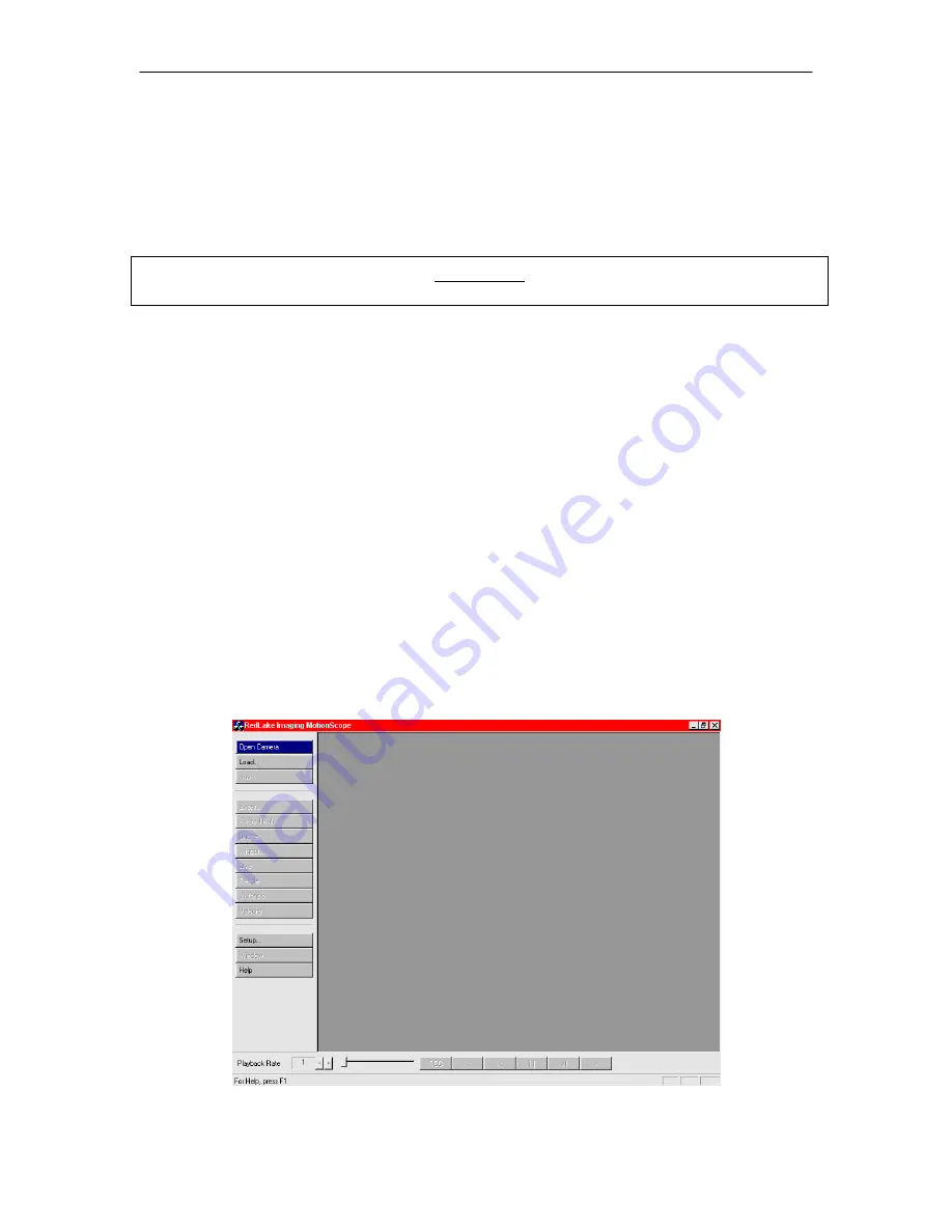
When the program loads, the application window comes up with four menu choices:
1. Open Camera. This shows a list of cameras for you to make a selection. Clicking on a
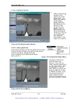
camera reference activates the Live/Setup mode and opens the camera window showing the
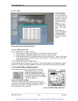
live camera picture. See Figure 3-1.
2. Load. This brings up an Open dialog box. You can load and view a recorded sequence from
a computer file on the computer disk or removable media.
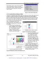
3. Setup. This brings up the Property dialog box that allows you to name the camera. See
Figure 3-2. This is very important if you are using more than one camera…Click on the Save
Camera Size and position check box.
4. Help. Shows the Software version.
Figure 3-1 The Initial Menu.
_____________________________________________________________________________
9400-0010 Rev S
3-2
02/15/02
Artisan Technology Group - Quality Instrumentation ... Guaranteed | (888) 88-SOURCE | www.artisantg.com


