Motion
Scope
â
PCI High Speed Video System
The system records the events and assigns a sequential frame number to each frame. However,
if the rate of recording frames varies from a record rate of 60, 125, 250, 500, 1000, 2000 or 8000
frames per second, the elapsed time (ET) displayed on the Playback window will not be the true
elapsed time.
1.3.4.1 Synchronizing two or more
Motion
Scope systems
The cameras should be connected as shown in Figure 1-6. One camera is designated the
Master and the other camera(s) are designated as Slave(s). Cameras are usually connected in
series. The most common series connection requires a BNC cable to connect the Phase Lock
Out from the Master or leading unit to the Phase Lock In connector on the next downstream unit.
Alternatively, The signal can be distributed to each camera using a tee connector. All master and
slave cameras must be set to the same Record Rate for accurate elapsed time (ET) indications.
1.3.4.2 Controlling the Record Rate of a Camera from an External Source
As a slave, the camera records one frame each time a phase lock signal is detected at the Phase
Lock In connector. A stream of signals can be supplied at any speed to record a series of frames
up to the maximum Record Rate set.
The Phase Lock In input is normally tied to +5 volts. The input signal to record a frame is a
square-wave signal rising from 0 volts to +5 volts. The input signal must pull the Phase Lock In
input to ground, and then provide a rising signal to record the frame. The elapsed time (ET)
indications for the slave units are not true when the frame rate does not equal the record rate set.
Refer to Section
2.8.5.1
for more details.
1.4 Marking a Frame (Data Record)
The
Motion
Scope provides a means to identify a frame or series of frames in the recorded
sequence. This Data Record feature, when turned on, places two square markers at the top left
corner of each frame. The Data Record inputs are held high (+5V TTL level) and the markers
show as white squares on each frame. A contact closure to ground pulls the inputs low and they
show as black squares.
These inputs must be enabled by switch SW-7 on the Controller rear panel. The Data Record
inputs (Input 0 and Input 1) are through BNC connectors on pigtails on the camera cable.
1.5 Recording a Sequence in the Image Memory
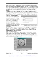
When the camera is turned on and the first sequence recorded in the image memory, the first
image is recorded in the Initial Frame, Frame 0. The system places the next images in Frames 1,
2 up to the last frame, and then records over Frame 0. The system records the latest video over
the oldest frame so that the total number of frames available is equal to the number of frames in
the image memory. See Figure 1-7.
1.5.1 Stop
Recording
When you click on Stop, the system stops recording
and goes into a pause mode, waiting for an
instruction for the next function. You may enter an
instruction to record again, playback from the image
memory, save the sequence or return to Live mode.
All images in the memory precede the active frame
when you clicked on Stop.
The first frame of the next recorded sequence
follows the last frame of the previous sequence.
Figure 1-7 The Image Memory.
_____________________________________________________________________________
9400-0010 Rev. S
1-5
OPERATOR'S INSTRUCTIONS
Artisan Technology Group - Quality Instrumentation ... Guaranteed | (888) 88-SOURCE | www.artisantg.com


