Red Jacket LPG Premier Скачать руководство пользователя страница 18

Introduction

System Protection

14

System Protection

Red Jacket recommends a complete system built around the pump to ensure safety, reliability, stability, and 
performance. If the entire system is calculated and built according to accepted specifications, the installation will 
operate for many years without requiring any form of maintenance.

There are two pump characteristics that can be checked if performance deteriorates:

1. Its output - flow rate versus pressure. 

2. Its electrical connections and amperage consumed under load.

Potential Problems

Red Jacket submersible LPG pumps are multi-stage centrifugal pumps. The advantage of the multi-stage 
technology is maximum performance by a minimum of energy, respectively 2.25 kW (3 hp) for the 21 stage 
Premier pump, 2.25 kW (3 hp) for the 17 stage Premier MidFlow pump and 3.75 kW (5 hp) for the 24 stage 
Premier HiFlow pump. During operation the pressure increases with approximately 50 kPa (7.25 psi) per stage up 
to the maximum design pressure of the pump respectively 1000 kPa (145 psi) for the Premier pump, 880 kPa 
(127 psi) for Premier MidFlow pump and 1220 kPa (180 psi) for Premier HiFlow pump. 

For all types of Red Jacket submersible LPG pumps the minimum differential pressure can never be below 400 
kPa (58 psi). This minimum required differential pressure is to guarantee that during operation all respectively 17, 
21 or 24 stages are submerged in the LPG liquid. Another basic rule for a centrifugal pump is that there must be 
sufficient liquid available by the inlet of the pump. The pump can only build differential pressure when the first 
stage of the pump is completely submerged in the liquid. This so-called NPSH (Net Positive Suction Head) is 127 
mm (5 inches) above pump inlet opening for all types Red Jacket submersible LPG pumps.

Cavitation is when the liquid flows with a velocity high enough to reduce the local pressure below vapor pressure 
forming small gas-filled bubbles. These gas-filled bubbles exhibit complex dynamics and erosive action on nearby 
surfaces.

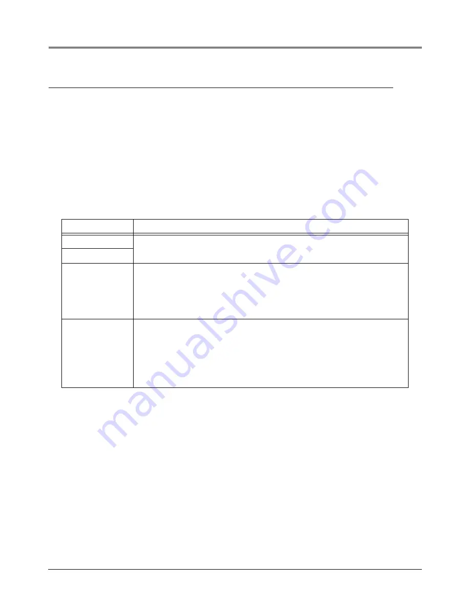
Table 5. Potential Performance Problems

Problem

Solution

Dry run

A control box with low pressure detection can detect both of these performance prob-
lems.

Cavitation

Equalization line in 
the manifold is too 
small

The Red Jacket LPG pump has an internal by-pass. A certain amount of LPG passes 
and cools the motor (self-maintaining principle) and exits the pump at the internal by-
pass. The motor’s heat is transferred to the liquid and is therefore warmer than the liq-
uid in the tank. Also this liquid has a higher vapor pressure than does the liquid in the 
tank. The equalization line between the manifold and the tank is to balance both liquid 
levels. If this equalization line is too small or even closed, the manifold can be emptied 
through the manifold inlet and it can cause a dry run or even cavitation.

Dirt in the tank

Small parts of LPG dust or iron oxide, which can normally be found in LPG, will not 
hurt the system. During operation those particles can, however, block the breather 
plugs at the inlet of the pump-motor, but when the pump is switched off a small amount 
of liquid will be pressurized back in the tank. This amount of liquid will clean the 
breather plugs again.

Of course, any form of dirt should be avoided and shortens the expected lifetime of the 
pump. It is recommended to install a strainer (100-micron) at the inlet of the storage 
tank to avoid dirt entering the tank during deliveries.

Содержание LPG Premier

Страница 1: ...Manual No 051 327 1 Revision N Installation Guide LPG Premier LPG Premier MidFlow LPG Premier HiFlow...

Страница 2: ...f any damages and or shortages within 30 days of receipt of the shipment as stated in our Terms and Conditions VEEDER ROOT S PREFERRED CARRIER 1 Fax Bill of Lading to V R Customer Service at 800 234 5...

Страница 3: ...ump Motor Unit 19 Fitting the Pump Motor Unit into the Manifold or Storage Tank 21 Electrical Connection 21 Determining Correct Motor Rotation 21 Three Phase Current Unbalance 21 Typical System Scheme...

Страница 4: ...e 9 Typical Scheme For A Direct Installation With Vertical Submersible Pump Motor Unit 27 Figure 10 Service Parts 31 Tables Table 1 LPG Pump Motor Unit Models 4 Table 2 Recommended Material List for D...

Страница 5: ...n through the conduit pipe The conduit pipe is mounted inside the product line and is sealed against the pumped liquid The electrical wires are mounted in a plug pigtail which provides a seal into the...

Страница 6: ...apors are extremely flamma ble WARNING Warning Alert read message and follow instructions to avoid serious injury death or substantial property damage TURN POWER OFF Live power to a device creates a p...

Страница 7: ...rlocked and are enclosed in a stainless steel shell There is not a requirement for initial bearing running in period for the Red Jacket submersible LPG pumps For all types of Red Jacket submersible LP...

Страница 8: ...ion with the pigtail discharge head consists of a metal body Ex d flameproof enclosure and electrical connections The wires in the connectors are cast in epoxy The rotor conductors are copper bars Tab...

Страница 9: ...ge using an L1 plug gauge Apply Loctite 565 570 or 577 thread sealant Butane and Propane resistant to both ends of the conduit pipe Direct Installation Installing the submersible pump directly into th...

Страница 10: ...stallation of Red Jacket LPG Pump Motor Unit FLANGED VALVE FLANGE VAPOR LINE LIQUID LINE WITH DIRECTION ARROW 4 5 3 4 VAPOR LINE 1 1 4 DISPENSING LINE 9 FILL 2 15 24 2 1 3 18 11 10 17 20 19 15 14 13 2...

Страница 11: ...e 5 if applicable 7 Flange 2 8 Kit conduit box 1 Red Jacket 114 115 5 9 Ball valve 2 Argus EK 71 10 Relief valve 1 4 Rego 3127 G 11 Remote control valve 3 4 Argus EK 71 Pneu Electrto 12 Internal bleed...

Страница 12: ...ified as an unfired pressure vessel and is designed according to regulations for Pressure Vessels The manifold must be suitable for the type of pump to guarantee the above described minimum requiremen...

Страница 13: ...Jacket LPG Pump Motor Unit FLANGED VALVE FLANGE VAPOR LINE LIQUID LINE WITH DIRECTION ARROW MANIFOLD 12a 31 7 8 3 4 VAPOR LINE 1 1 4 DISPENSING LINE 30 15 18 FILL 2 21 33 5 2 1 4 3 34 6 29 24 17 16 23...

Страница 14: ...5 2h Regulations 10 Flange 5 11 Ball valve 1 2 Argus EK 71 12 Equalization line acc 8 5 2c Regulations 12a Excess flow valve 3 4 Rego A3272 G if applicable 13 Flange 2 14 Kit conduit box 1 Red Jacket...

Страница 15: ...an itemized list for the Figure 3 manifold Figure 3 Horizontal Manifold With Red Jacket LPG Pump Motor Unit 31 Relief valve 1 4 Rego 3127 G 32 Manhole cover NW 420 525 mm 33 Check valve 2 Rego A3186...

Страница 16: ...9 Excess flow valve 3 4 Rego A3272 G 10 Flange 5 11 Ball valve 3 4 Argus EK 71 12 Vapor return acc 8 5 2c Regulations 13 Flange 2 14 Kit conduit box 1 Red Jacket 114 115 5 15 Ball valve 2 Argus EK 71...

Страница 17: ...the tank and the pressure of the manifold to overcome running dry of the submersible pump by low liquid level and to equalize the pressure during refill of the installation The design of the equalizat...

Страница 18: ...etely submerged in the liquid This so called NPSH Net Positive Suction Head is 127 mm 5 inches above pump inlet opening for all types Red Jacket submersible LPG pumps Cavitation is when the liquid flo...

Страница 19: ...and it is to be recommended to include in the installation a so called Low pressure Dry Run protection unit preferably based on pressure technology When installed according to the specifications the...

Страница 20: ...he manifold s inlet opening 4 Installing the submersible pump directly into the storage tank without a manifold is allowable only when permitted by local regulations In such installations the clearanc...

Страница 21: ...2 456 50 5 4 20 8 4 10 4 3 7 P500V17 24 5 0 3 7 3 342 456 50 8 8 33 4 9 5 9 3 7 Part Number Model Weight kg lbs 410687 001 LPG 21 10 21 410687 002 LPG 24 10 21 410687 003 LPG 17 11 24 410686 001 P300V...

Страница 22: ...esence of an authorized technician System Description The Red Jacket submersible LPG pump is fitted into the special developed manifold which has to be installed into one of the manholes of the storag...

Страница 23: ...sket 1 Pigtail connector 14 AWG 3 meter 10 feet 1 Socket screws and lock washers 5 16 18 inch 4 of each O ring Viton 53 6 x 2 6 mm 2 11 x 0 103 in 1 This Installation manual 1 rj 051 327 fig2 eps Prem...

Страница 24: ...ligning the pump shaft with the motor coupling Secure the pump to the motor by using the cap screws and lock washers supplied with the pump Using a torque wrench the screws should be tightened to 28 3...

Страница 25: ...ure with the ball valve closed Next reverse power leads at magnetic starter Repeat pressure test as described above If results are higher than the first test the rotation during the second test is cor...

Страница 26: ...as been taken in the preparation of this manual Veeder Root shall not be liable for any misunderstanding errors and or loss or defects arising from the use of this manual Design codes and local regula...

Страница 27: ...the data in Table 7 System Components List of appurtenances as shown on the typical schemes of LPG service station underground and aboveground storage tank with submersible pump Table 7 Required Data...

Страница 28: ...uired Optional 19 Excess flow valve equalization line 3 4 Optional 20 Insulation joint 2 21 Insulation joint 1 1 4 22 Insulation joint 3 4 23 Filling hose 3 4 24 Filling nozzle 3 4 25 Break away coupl...

Страница 29: ...e length as short as possible diameter minimum 8 mm 0 31 in Excess flow valve If design required in equalization line minimum 78 liter min 20 gallon min Premier Hiflow Nomenclature LPG500V17 24 Excess...

Страница 30: ...Premier Midflow Nomenclature LPG300V17 17 Excess flow valve Inlet minimum 462 liter min 122 gallon min liquid Ball valve 2 Manifold 6 9 in 175 mm minimum Outlet 1 2 in Vapor return line in Excess flow...

Страница 31: ...ported by three support arms a the inlet b discharge head and c at the pump flange i e DSI PA PE 4 38 Pipe Isolator Manifold must be installed 4 5 upwards to avoid vapor lock in manifold Table 10 Mini...

Страница 32: ...ttings are tight to prevent leaks 2 Fill the tank and manifold with nitrogen until pressure reaches 100 kPa 14 7 psi Relieve pressure until it reduces to 15 kPa 2 1 psi 3 Repeat the filling with nitro...

Страница 33: ...and fill the manifold with nitrogen pressure max 1000 kPa 145 psi until you hear the nitrogen bubbling from the inlet of the manifold 6 Close the inlet ball valve and purge connection secure the inlet...

Страница 34: ...he pressure gauge in the liquid line when LPG vapor comes out 8 Open the ball valve of the manifold and secure the ball valve against closing 9 Connect the pressure gauge 10 Connect the power cable in...

Страница 35: ...equirements the pump motor unit should be removed from the storage vessel and inspected A Red Jacket submersible Premier Premier Mid Flow or Premier Hi Flow LPG pump is not repairable The pump and mot...

Страница 36: ...cle tank is full Contents gauge No problem exists Differential Pressure Low Discharge head or pump is loose creating pressure leak Pump motor assembly Pull pump motor assembly check condition of O rin...

Страница 37: ...sure in vehicle tank Vehicle tank temperature Cool tank or reduce number of open nozzles Pump Not Running Contactor coil is not engaged Emergency stop dispenser switch and contactor wiring Close all s...

Страница 38: ......

Страница 39: ......

Страница 40: ...For technical support sales or other assistance please visit www veeder com...

Отзывы: