background image

3

Part Description 

Part Number

THE SYMBOLS AND THEIR MEANINGS SHOWN BELOW MAY BE USED THROUGHOUT THIS MANUAL. PLEASE ENSURE THAT YOU 
TAKE THE APPROPRIATE ACTION WHEREVER THE WARNINGS ARE USED.

Explanation of Symbols

i

Kg

i

Kg

i

Kg

i

Kg

i

Kg

i

Kg

i

Kg

i

Kg

Mandatory 
Instructions

Warning

Read and fully understand the instruction manual 
before attempting to use the machine.

Indicates an instruction that requires particular attention

Wear protective eyewear

Use respiratory protective equipment

Use suitable protective footwear

Use hearing protection

Use protective work gloves

Indicates a risk of severe personal injury or 
damage to the machine

Indicates a risk of severe personal injury 
from electrical shock

Risk of personal injury from lifting of heavy items

Indicates a risk of severe personal injury from 
airborne objects

Risk of fire

i

Kg

i

Kg

i

Kg

i

Kg

Содержание TS250C

Страница 1: ...ar safety glasses when using woodworking equipment Always read the instructions provided before using woodworking equipment i Kg Version 3 0 January 2013 To register this product please visit www recordpower info It is important to register your product as soon as possible in order to receive efficient after sales support and be entitled to the full 5 year guarantee Your statutory rights are not a...

Страница 2: ... Specification page 10 4 Saw Unit Assembly page 11 5 Rip Fence Assembly page 17 6 Final Assembly page 19 7 Operation Sawing Practice page 20 8 Dust Extraction page 24 9 Maintenance page 25 10 Electrical Connection Wiring Diagram page 27 11 Parts Lists Diagrams page 28 Consumable Spare Parts Quick Find Part Description Part Number Table insert Blade guard Blade guard extraction hose Riving knife Ha...

Страница 3: ...o use the machine Indicates an instruction that requires particular attention Wear protective eyewear Use respiratory protective equipment Use suitable protective footwear Use hearing protection Use protective work gloves Indicates a risk of severe personal injury or damage to the machine Indicates a risk of severe personal injury from electrical shock Risk of personal injury from lifting of heavy...

Страница 4: ...tation of the machine is required then all precautions relating to the installation and handling of the machine apply In addition ensure that any vehicles or manual handling equipment used for transportation are of adequate specification 6 The machine should be level and stable at all times When using a leg stand or cabinet base that is designed to be fitted to the machine always ensure that it is...

Страница 5: ... area always use a push stick to feed the work piece in to the blade or cutting tool The push stick should have a minimum length of 400 mm If the push stick becomes damaged replace it immediately Use extra supports roller support stands etc for any work pieces large enough to tip when not held down to the table top Do not use another person as a substitute for a table extension or as additional su...

Страница 6: ...urn the machine ON and OFF Have defective switches replaced by a qualified person 31 Warning The use of any accessory or attachment other than those recommended in this instruction manual or recommended by our Company may present a risk of personal injury or damage to the machine and invalidation of the warranty 32 Have your machine repaired by a qualified person This machine complies with the rel...

Страница 7: ...ly replace the blade immediately Check that the saw blade is within the minimum and maximum diameters permissible on the machine as detailed in the manual Check that the bore of the saw blade matches the diameter of the spindle of the machine Never attempt to modify the saw blade to make it fit the machine Check that the saw blade has a speed rating higher than 5000 rpm and complies with BS EN847 ...

Страница 8: ...been purchased from a retailer the 5 year guarantee is transferable and begins on the date of the first purchase of the Product and in the event of a claim under this guarantee proof of the original purchase date will be required to validate the warranty period 2 Claims Procedure 2 1 In the first instance please contact the Authorised Dealer who supplied the Product to you In our experience many i...

Страница 9: ...before unpacking to have plenty of paper towels or cloths available to clean off the rust preservative Contents of the shipment 1 TS250C Table Saw 2 Sliding Table 3 TS200 E MK2 Right hand extension table optional accessory 4 TS250C W Wheel kit optional accessory 1 3 4 2 ...

Страница 10: ...Full load current 9 1 A Weight 110 kg Dimensions not including the sliding carriage 900 mm height x 625 mm width x 675 mm length Dimensions of sliding beam 1050 mm length x 215 mm width Sliding carriage stroke max sheet capacity 620 mm Noise emission Sound power level 100 dB A Sound pressure level 90 dB A A Extraction Hose B Blade C Crown Guard D Rip Fence E Main Table F Blade Raise fall G Switch ...

Страница 11: ...try This information however will enable the user of the machine to make a better evaluation of the hazard and risk Dust Collection Proper dust extraction eliminates the risks of dust inhalation and aids better functioning of the machine The table lists the minimum air flow and speed values referenced to each single extraction operation Ensure that the extraction system to be used guarantees these...

Страница 12: ...read through the extraction hole in the side of the machine Fig 4 2 4 1 Fitting the handwheel Attached the handwheel for blade tilt and rise fall with Hex wrench Fig 4 1 2 Fit the extraction port over the end of the hose and clip into place Fig 4 3 3 Secure the extraction connector to the end of the hose using the jubilee clip Fig 4 4 Jubilee clip Fig 4 4 Extractor connector ...

Страница 13: ...ade to ensure that the gap is equal along the full diameter of the blade When satisfied that the table is correctly adjusted tighten the 4 socket head screws Fig 4 7 Allen bolts and washers 4 3 Cabinet Stand Assembly Fig 4 5 Tools needed 10mm 13mm Spanner Assemble the four panels A B C D as shown using M6 x 15 mm bolts M6 washers M6 nuts Ensure that the front panel A and rear panel C are correctly...

Страница 14: ...achine Fig 4 9 but do not remove Adjust the table as necessary and re tighten the domed nuts if the rear of sliding table is not correctly adjusted loosen the two domed nuts at the rear of the machine Fig 4 10 but do not remove Adjust the table as necessary and re tighten the domed nuts Fig 4 10 Front Adjustment Nuts Rear Adjustment Nuts When the tables are at the correct height check the sliding ...

Страница 15: ... the tables as possible Tip The success of the table levelling procedure largely depends on the adjustment of the mounting bolts The smaller the movement required the tighter the bolts should be However the whole procedure really does depend on feel If the table isn t moving enough when tapped slacken the bolts slightly If it is moving too much tighten them slightly Tip Level one end at a time whe...

Страница 16: ...16 4 Saw Unit Assembly cont 4 7 Fitting the Crown Guard Hook the crown guard into the keyway on top of the riving knife Fig 4 17 and tighten into position Fig 4 18 Fig 4 17 Fig 4 18 ...

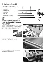
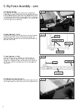
Страница 17: ...ths of bar is the same as described below 5 3 Fixing the Fence Scale Fig 5 2 Locate fence scale onto the table and fix with two pan head screws four pan head screws for optional table extension fence scale Fig 5 2 5 2 Fixing the Fence Bar Locate fence bar onto the table Fig 5 1A and fix with the two fence fixing bar nuts and washers four fence fixing bar nuts and washers for optional table extensi...

Страница 18: ... for use when making bevelled cuts with the blade tilted or when working with small workpieces Fence Rail Fence Movement Adjustment Nuts Adjustment Fig 5 5 5 7 Fence Alignment 2 Fig 5 6 Check that the fence is 90º to the table using a suitable square If no adjustment is needed fully tighten the fence bar nuts If adjustment is required this is achieved by raising or lowering either side of the fenc...

Страница 19: ...to the rear corner of the table or optional table extension Fig 6 1 2 Now attach one end of the hose to the crown guard Fig 6 2 3 Hook the hose over the hose support and feed underneath the table to connect with the main extraction outlet Fig 6 3 U piece Hose Support Main extraction outlet Fig 6 1 Fig 6 2 Fig 6 3 ...

Страница 20: ...wn guard and riving knife in position Always ensure that the crown guard and riving knife are correctly adjusted to suit the size and type of workpiece and that they are fully secured with the original fixings supplied 7 Operation Sawing Practice TABLE 1 Basic applications Ripping When the timber is cut with the grain use the rip fence for this application Cross Cutting When the timber is cut acro...

Страница 21: ...ing both soft and hardwoods provides protection from kickback Suitable for cross cutting and gives a fine finish on man made sheet material and laminates Suitable for cross and cutting gives a fine finish on man made sheet material and laminates Triple chip teeth reduce breakout on the material When choosing a blade for a table saw always ensure that it is a hard bodied blade soft bodied blades ar...

Страница 22: ...ing hand should never be closer than is necessary to the front of the saw and hands should never be in line with the saw blade A push stick should always be used to remove the cut piece from between the saw blade and fence Setting the Saw Guard The saw guard should be adjusted as close to the workpiece as possible Fig 7 8 Setting the Rise Fall The rise and fall must be adjusted so the saw guard is...

Страница 23: ... red button marked O on the switch If the blade is trapped within the work piece it may be necessary to prize the work piece apart slightly using a suitable lever in order to free the blade To re start the machine press the green button marked I on the switch In the Event of a Power Failure The table saw is fitted with a no volt release NVR switch to protect the user against automatic starting of ...

Страница 24: ... e if one motor is switched off for 20 minutes then the other can be used thus enabling continuous usage Or both motors can be used simultaneously giving maximum suction but in this mode the extractor must be switched off for 20 minutes every hour 0 5 micron filtration suitable for MDF DX5000 High Filtration Dust Extractor Bag type extractor 200 litre capacity twin 1 kW motor suitable for heavy us...

Страница 25: ...e blade from the spindle Fig 9 7 The blade can now be replaced 8 Feed the new blade on to the spindle ensuring that it is seated firmly on the hub 9 Replace the bush washer and nut and using a spanner turn the nut anti clockwise to tighten it At this point the tommy bar should have turned with the blade and be tight up against the spindle housing to create an anchor to turn against 10 Replace the ...

Страница 26: ...saw unit Tensioning the belt 1 When tensioning the belt the three motor mounting bolts must be slackened Fig 9 8A and Fig 9 8B 2 Slacken the three bolts and pivot the motor to the right to increase tension Fig 9 9 When the desired tension is achieved retighten the three bolts to secure the setting Fig 9 8A Fig 9 8B Bolt 1 Bolt 2 Bolt 3 Fig 9 9 ...

Страница 27: ...63 plug for use in the UK always ensure that it is fitted with a fuse conforming to BS1362 appropriate to the rating of the machine If replacing the original fuse always fit a fuse of equivalent rating to the original Never fit a fuse of a higher rating than the original Never modify the fuse or fuse holder to accept fuses of a different type or size Where the current rating of the machine exceeds...

Страница 28: ...28 11 Parts Lists Diagrams ...

Страница 29: ...29 11 Parts Lists Diagrams cont ...

Страница 30: ...30 11 Parts Lists Diagrams cont ...

Страница 31: ...31 11 Parts Lists Diagrams cont ...

Страница 32: ...22 23 24 25 26 27 28 29 30 31 32 33 34 35 36 37 38 39 40 41 42 43 44 45 46 47 48 49 50 51 52 53 54 55 56 Tube Quill tube I Screw M8X20 square nut Flat washer Spring washer 8 Angle rotating shaft Tube circlip Dust collecting tube Motor Motor pulley Washer Big washer Hex bolt Motor mounting plate Gear rod Circlip 12mm Circlip 22mm Bearing Bearing base Screw Big handwheel Wheel handle Screw Screw Rod...

Страница 33: ...17 118 119 120 121 122 123 124 125 126 127 128 129 130 131 132 133 134 135 136 137 138 139 140 141 142 143 144 145 146 147 148 Fence Carriage bolt M6X30 T bracket Mitre gauge Countersunk head screw M6X70 Nut Right end cap Tapping screw ST4 2X9 5 Left end cap Countersunk head screw M6X50 Flat washer 6 Flat washer 6 Flat washer 4 Screw M4X12 Indicator base Roll pin Indicator Screw M4X8 Adjusting han...

Страница 34: ...Ї ر 4 ຏ ࣖܡֽ ן ຽ ď Đ ဈ Cabinet stand Ref No Description Ref No Description Stand front panel Hex nut M6 Washer 1C 2C 3C Hex bolt M6x15 Stand side panel Rubber feet 4C 5C 6C Ref No Description Stand front panel Hex nut M6 Washer Hex bolt M6 x 15 Stand side panel Rubber feet 1 2 3 4 5 6 ...

Страница 35: ... LOW VOLTAGE DIRECTIVE 2006 95 EC ELECTROMAGNETIC 2004 108 EC COMPATIBILITY DIRECTIVE EN 55014 1 2006 EN 61000 3 2 2006 EN 61000 3 3 1995 A1 A2 EN 55014 2 1997 A1 and conforms to the machinery example for which the EC Type Examination Certificate No BM50170597 AN50170595 AE50103166 has been issued by TUV Rheinland Product Safety GmbH at Am Grauen Stein D 51105 Cologne Germany and complies with the...

Страница 36: ...cordpower co uk Eire Record Power Ltd Centenary House 11 Midland Way Barlborough Links Chesterfield Derbyshire S43 4XA Tel 01246 571 020 Fax 01246 571 030 www recordpower co uk Australia Tools 4 Industry Po Box 3844 Parramatta 2124 Tel 1300 124 422 Fax 1800 262 725 www recordpower com au New Zealand Tools 4 Industry Po Box 276079 Manukau City 2241 Tel 0800 142 326 Fax 09 2717 237 www recordpower c...

Отзывы: