P a g e
| 5
Bee9 User's Manual
Reach/BTX
3.
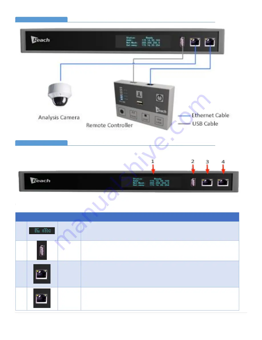
Bee9 Connectivity (Front Panel)
4.
Detailed Connectivity Description
5.
Front Panel
No.
Image
Item
Description
1
LCD
Screen
This display will provide current status of the system, its network connections,
and provide confirmation of recording mode. When the Bee9 is powered on, the
display will indicate the startup procedure.
2
Control
Panel
USB Port
Connect a USB-A to USB-A cable (provided) to this port and the remote control
panel. This port does not provide power to an external disk drive powered by
USB!
3
LAN Port
for
Analysis
Camera
This LAN port is used to connect to the system analysis camera. The IP address is
preset within the Bee9. No manual setting is required.
Note: The analysis camera must be connected directly. Ethernet extenders
CANNOT be used.
4
Serial
Port
Connected to the serial port of the Remote Control Panel. (Note: Even though
connectivity is by an Ethernet cable, this connection utilizes RS-485 protocol.)
Bee9 Connectivity (Front Panel)
Section 3
Bee9 Connectivity Detail (Front Panel)
Section 4


