RDS PS 8000 Скачать руководство пользователя страница 18

2 - Operation

2.6 

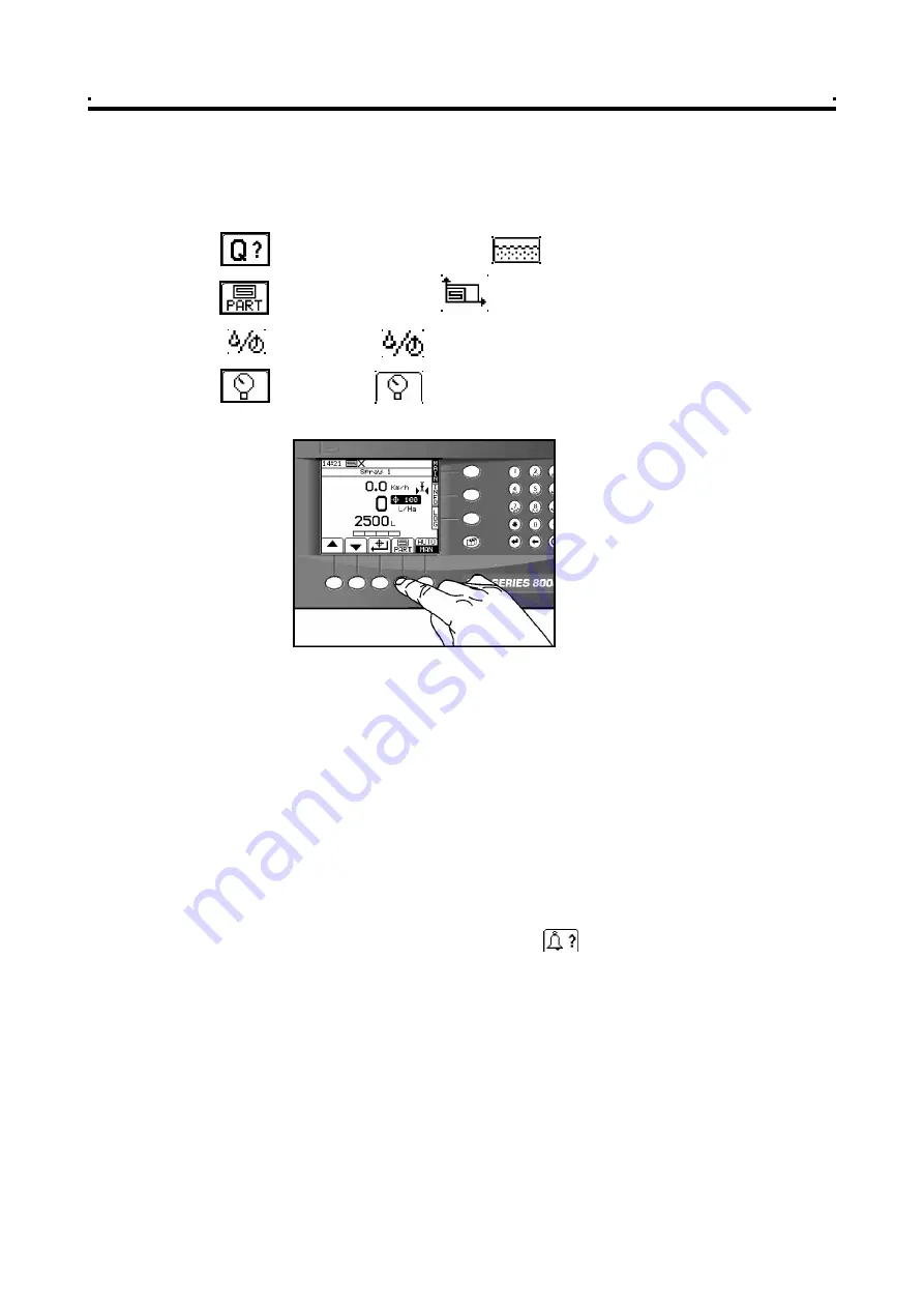
"MAIN" screen display options 

In  addition  to the  Application  rate  and  Forward  Speed  display,  on  the  appropriate

MAIN screen page for each machine enabled, you can select between,

Volume remaining in tank

  (                 litres or  gallons)

Accumulated area

(                 hectares or acres)

Flow rate

(                 litres/min or gallons/minute)


Pressure

  (               bar or psi - only on systems fitted with a pressure sensor)

2.7 

Tank Contents

The 

Apollo  8000

automatically  calculates  the  volume  of  liquid  remaining  in  the

appropriate  tank.  The  calculation  is  based  on  the  full  tank  volume  which  is

programmed via the "INFO" screen.  You can also programme an alarm threshold so

that the instrument will warn you when the tank volume is getting low. 

When the alarm threshold is reached (e.g. 200 litres), first of all the screen will change

to show the alarm screen and the message '

TANK # LOW

'. The instrument will beep

continuously. Press any of the lower 'OK' keys to cancel the alarm screen and return

to the 'MAIN'  operating screen. An  alarm bell icon in the upper right hand corner of

the  screen  will  continue  to flash  and  the  instrument  will  beep  every 5  seconds  to

remind you of the alarm condition.

NOTE: 

If the instrument flashes the alarm  bell icon as above, at any time you can re-identify

the cause of the alarm by pressing the            key on the INFO screen.

The screen will change to show the alarm screen and the message '

TANK # EMPTY'

'

once the tank contents register reaches zero. Again, press any of the lower 'OK' keys

to cancel the alarm screen to return to the 'MAIN' operating screen, and the alarm will

continue as above.

The tank contents register must be reset manually after re-filling the tank unless your

system includes the optional 

Tank Inflow Sensor and Flow Shutoff Valve

. When fitted

this  enables  the instrument  to automatically monitor re-filling and  cut off the  inflow

when the tank is full.

Figure 13

Selecting the display option

on the MAIN screen


      18   

Содержание PS 8000

Страница 1: ...PS 8000 APOLLO DELTA 34 SPRAYER CONTROLLER Operation RDS Part No Doc Issue Software Issue S DC 500 10 221 4b 10 8 01 PS515 002 rev 27 Apollo PS521 000 rev 10 Delta 1...

Страница 2: ...and functions of the Precision Farming System the System are limited as set out in the specification of the System details of which are contained in the Help files and product literature and which mus...

Страница 3: ...2 Using the Nozzle Wizard 15 2 3 3 Editing a Preset Nozzle Type 15 2 3 4 Programming the Product Density 16 2 4 Automatic Rate Control 17 2 4 1 Setting the Target Rate 17 2 4 2 Overriding the Target r...

Страница 4: ...iable rate instructions to other control systems including Vicon Bogballe and Amatron systems as well as acting on variable rate instructions received from Fieldstar Soyl Opti Agrocom ACT and Hydro N...

Страница 5: ...yer fitted with an RDS distribution system On changing sprayers the appropriate tank is enabled from the Machine Options screen in the calibration menu You must re configure the boom setup as required...

Страница 6: ...on the PCMCIA card The job summary data is also appended to this file which can be viewed in PLOT PLAN VRT Variable rate treatment Control Mode Apollo only This enables the system to be controlled vi...

Страница 7: ...to denote their function 1 6 2 The MAIN screen page Single implement operation The instrument will always default to the MAIN screen on startup The MAIN screen displays the following information figur...

Страница 8: ...No Module Module but no card OK iii if a GPS signal is being received Apollo only No Position Standalone No Diff Full DGPS iv if the area distance is being accumulated Apollo Delta 34 No accumulation...

Страница 9: ...pplication mode AUTO or MAN and alter the target rate AUTO mode or actual application rate MAN mode for each tank Multi tank display and settings From the multi tank page you can alter the target rate...

Страница 10: ...ollo only This page controls data logging Field Summary data and P F functions when the Data Card Module is connected and enabled and data transfer e g printing a job summary 1 Overview Figure 6 The I...

Страница 11: ...to select the required letter Some keys have additional special characters not shown on the key legend The key will either toggle between lower and upper case characters or when preceeding a numerica...

Страница 12: ...lease refer to the Calibration manual The units are Function Units Metric U K Imperial ForwardSpeed k m hr miles hr Application rate l itres ha g allons acre Flow rate l itres min gallons min Part Tot...

Страница 13: ...own arrow key move the screen cursor opposite the product for that tank figure 9b For any tank you can programme and calibrate up to 8 different products A to H NOTE 2 By default the products are labe...

Страница 14: ...rget Speed The centre of the bow tie display indicates the target speed for optimum nozzle performance The operating range of the nozzle is based on the target speed There are 8 pre programmed ISO sta...

Страница 15: ...arted with the sprayer stationary To stop speed simulation press the key or move the vehicle a short distance 2 3 2 Using the Nozzle Wizard 1 Set your Target Speed as above 2 Key in the target applica...

Страница 16: ...ensity for the selected product is anything other than 1 00 the instrument will display the icon on the main screen 1 Press to select the SETUP screen 2 Press to select the PRODUCT SELECTION screen fi...

Страница 17: ...instrument will beep continuously Press any of the lower OK keys to cancel the alarm screen and return to the MAIN operating screen An alarm bell icon in the upper right hand corner of the screen will...

Страница 18: ...ill beep continuously Press any of the lower OK keys to cancel the alarm screen and return to the MAIN operating screen An alarm bell icon in the upper right hand corner of the screen will continue to...

Страница 19: ...screen cursor using the arrow keys and enter values via the numeric keypad 4 Press to reset to the full tank volume 5 Confirm the alarm volume is OK typically the volume needed to spray a single bout...

Страница 20: ...nction In addition the area and volume will be recorded to the TOTAL memoryregister 1 Select the INFO screen to display the accumulated totals and the RPM display NOTE If more than one tank is enabled...

Страница 21: ...ficient pump capacity low pump speed low or empty tank blocked filters or incorrect jets Press any of the lower OK keys to cancel the alarm screen and return to the MAIN operating screen An alarm bell...

Страница 22: ...k session in the internal memory and subsequently download directly to a PC or print to an RDS ICP200 In Cab Printer The amount of summary data for each job is small and it is saved in the internal me...

Страница 23: ...the appropriate farm field description in turn from the lists NOTE If a treatment plan is to be loaded and there is more than one machine i e distribution system enabled the SELECT MACHINE page is no...

Страница 24: ...al the treatment rate will revert to the Base Rate specified in the plan Application Rate Outside the Field Boundary If you go outside the field boundary but are still within the treatment rectangle a...

Страница 25: ...dual requirements e g Operator name Wind Speed Air Temperature Growth Stage Product etc Entering extended data is optional The functions are F1 to F12 by default You can re programme the default funct...

Страница 26: ...nt position If you selected the LOG TREATMENT option from the LOG screen page the track data is saved to a dynamic logging file on the data module which can then be viewed in PLOT PLAN 3 2 7 Display G...

Страница 27: ...3 Select the logging option LOG TREATMENT 4 When prompted enter the FARM NUMBER and FIELD NUMBER reference The EXTENDED DATA FUNCTIONS page is then displayed If you don t wish to programme any extend...

Страница 28: ...ge is displayed fig 17 3 Select the logging option LOG SUMMARY ONLY 4 When prompted enter the FARM NUMBER and FIELD NUMBER reference The EXTENDED DATA FUNCTIONS page is then displayed If you don t wis...

Страница 29: ...lected summary 3 5 2 Summary Data Formats You can download the data to Data Card Module Each summary is saved as a text file e g JOB0001 TXT and is formatted the same as a printed job ticket ICP 100 o...

Страница 30: ...ues Comments Operator Transmit Time and Date Not included in CSV format 3 5 3 Select and Print Download Job Summaries 1 From the View Data page fig 26 27 press the key 2 Press to select the last summa...

Страница 31: ...7 12 99 Full document update p 1 26 inc for software version PS504 010 Issue 3 20 3 01 Update for S W PS515 002 ver 004 Issue 4 19 7 01 U pdate for S W PS515 002 rev 25 Delta 34 Issue 4b 10 8 01 PF r...

Отзывы: