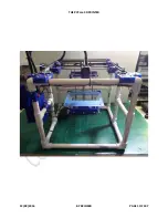
THE PVCore 3D PRINTER
12/28/2016
BY RCJOSEB
PAGE 1 OF 107
Страница 1: ...THE PVCore 3D PRINTER 12 28 2016 BY RCJOSEB PAGE 1 OF 107 ...
Страница 2: ... come without instructions or have to be heavily modified to work properly All of these factors lead to either an unfinished 3D printer or a big paper weight That is when I decided to design a simple PLA only 3D printer for the beginner 3D printer enthusiast The following are a few design concepts I had in mind and tried to adhere to Half inch PVC pipe and connectors for the frame o It s cheap and...
Страница 3: ...at I am getting burnt I will remove the guides completely from my blog in a heartbeat and then everyone will suffer So let s be nice here and just link the guides back to my blog The guide is for personal use only by the end user to assist in building the PVCore The guide cannot be posted on any site other than my blog The guide can only be linked directly to my blog Do not claim ownership of the ...
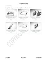
Страница 4: ...to length JB Weld ClearWeld or other similar epoxy Hammer or rubber mallet Scrap cardboard Popsicle stick Phillips screwdriver Pliers Super glue Some type of polish for steel Waterproof resistant high grit sandpaper Measuring tape or ruler Felt tip marker or pen 1 8 drill bit Drill Paper towels 5 16 wrench or socket 3mm Hex wrench or Allen key Rags 3 in 1 oil or silicone spray WD40 ...
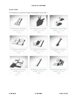
Страница 5: ...THE PVCore 3D PRINTER 12 28 2016 BY RCJOSEB PAGE 5 OF 107 3D PRINTED PARTS The 3D printed parts are referenced throughout this build guide using letter codes ...
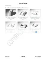
Страница 6: ...THE PVCore 3D PRINTER 12 28 2016 BY RCJOSEB PAGE 6 OF 107 3D PRINTED PARTS The 3D printed parts are referenced throughout this build guide using letter codes ...
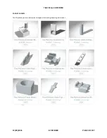
Страница 7: ...THE PVCore 3D PRINTER 12 28 2016 BY RCJOSEB PAGE 7 OF 107 3D PRINTED PARTS The 3D printed parts are referenced throughout this build guide using letter codes ...
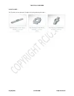
Страница 8: ...THE PVCore 3D PRINTER 12 28 2016 BY RCJOSEB PAGE 8 OF 107 3D PRINTED PARTS The 3D printed parts are referenced throughout this build guide using letter codes ...
Страница 9: ...THE PVCore 3D PRINTER 12 28 2016 BY RCJOSEB PAGE 9 OF 107 3D PRINTED PARTS The 3D printed parts are referenced throughout this build guide using letter codes ...
Страница 10: ...THE PVCore 3D PRINTER 12 28 2016 BY RCJOSEB PAGE 10 OF 107 3D PRINTED PARTS The 3D printed parts are referenced throughout this build guide using letter codes ...
Страница 11: ...ns to each BEARING TYPE PRO CON Metal Lasts longer than plastic Can bind due to poor quality If good quality will be very smooth Can be noisy Plastic Quiet Lasts less than metal Very smooth Can warp and bind I ran into binding issues with both types of bearings but was able to resolve them by polishing the smooth rods and reducing any burrs or scratches The 3D printed bearings worked very well for...
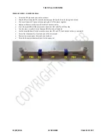
Страница 12: ...ipe for fronts FF 14 x 5 25 PVC pipe for verticals FV 10 x 6 625 PVC pipe for side horizontals FSH 06 x 6 5 PVC pipe for back horizontals FBH 01 x cross shaped slip connector FC 08 x ninety degree side outlet slip elbows FE 12 x T slip connectors FT 02 x 3D printed parts Z1 JB Weld ClearWeld 5 minute epoxy or similar epoxy not shown ...
Страница 13: ... pieces together Apply a small amount of epoxy to the inside of each connector Insert the pipes FBH all the way into the connectors FE and FT until they stop Use a hammer or mallet to drive the pipes FBH further in if needed Lay the assembly down flat and move the connectors FE and FT front to back so there is no wobble Ensure that the assembly is level and even all the way around Remove any exces...
Страница 14: ... to the inside of each connector Insert the pipes FBH all the way into the connectors FE and FT until they stop Use a hammer or mallet to drive the pipes FBH further in if needed Lay the assembly down flat and move the connectors FE and FT front to back so there is no wobble Ensure that the assembly is level and even all the way around Remove any excess epoxy that may have oozed out Put aside the ...
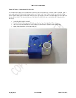
Страница 15: ...ng holes all the way through the pipe FBH and connector FE to the other side Each side is drilled separately to ensure the holes line up with each other The red arrow points to a hole that will be drilled later when a vertical pipe FV is attached to the elbow FE Orient the upper back wall as shown Place the 3D printed bearing mounts B1 underneath and on top of the right elbow FE as shown Use a 1 8...
Страница 16: ... will be drilled later when a vertical pipe FV is attached to the elbow FE Orient the upper back wall as shown Place a 3D printed bearing mount B1 on top of the right elbow FE as shown Use a 1 8 drill bit and the mount B1 as a guide to drill the lower holes as shown by the yellow arrows Repeat the above steps for the left side elbow FE ...
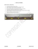
Страница 17: ...y to the inside of each connector Insert the pipes FBH all the way into the connectors FC and FT until they stop Use a hammer or mallet to drive the pipes FBH further in if needed Lay the assembly down flat and move the connectors FC and FT front to back so there is no wobble Ensure that the assembly is level and even all the way around Remove any excess epoxy that may have oozed out Put aside the...
Страница 18: ...lue all of the pieces together Apply a small amount of epoxy to the inside of each connector Insert the pipes FV all the way into the wall section connectors FE and FT until they stop Use a hammer or mallet to drive the pipes FV further in if needed Ensure that the assembly is level and even all the way around Remove any excess epoxy that may have oozed out Put aside the completed assembly and let...
Страница 19: ... a small amount of epoxy just enough to glue all of the pieces together Apply a small amount of epoxy to the inside of each connector Insert the pipes FSH all the way into the elbows FE until they stop Use a hammer or mallet to drive the pipes FSH further in if needed Remove any excess epoxy that may have oozed out Put aside the completed assembly and let the epoxy set ...
Страница 20: ...MOUNT HOLE Place a 3D printed bearing mount B1 underneath the top right elbow FE as shown Use a 1 8 drill bit and the mount B1 as a guide to drill the lower hole as shown by the red arrow Repeat the above steps for the top side of the elbow FE Repeat the above steps for the left elbow FE ...
Страница 21: ... connector Insert the pipes FSH all the way into the connectors FT until they stop Use a hammer or mallet to drive the pipes FSH further in if needed Insert the pipes FV all the way into the connectors FT until they stop Use a hammer or mallet to drive the pipes FV further in if needed Lay the assemblies down flat and move the connectors FT front to back so there is no wobble Ensure that the assem...
Страница 22: ...own Mix a small amount of epoxy just enough to glue all of the pieces together Apply a small amount of epoxy to the inside of each connector FT Insert the pipes FSH all the way into the connectors FT until they stop Use a hammer or mallet to drive the pipes FSH further in if needed Remove any excess epoxy that may have oozed out Put aside the completed assembly and let the epoxy set ...
Страница 23: ... the pipes FV further in if needed Lay the assembly down flat and move the connectors FE and FT front to back so there is no wobble Insert the pipes FF all the way into the connectors FE until they stop Use a hammer or mallet to drive the pipes FF further in if needed Insert the pipes FSH all the way into the connectors FE until they stop Use a hammer or mallet to drive the pipes FSH further in if...
Страница 24: ...ot be drilling holes all the way through the pipes FF and FSH and connector FE to the other side Each side is drilled separately to ensure the holes line up with each other Decide which side of the front assembly is going to face forward and orient it as shown above Place the 3D printed motor parts M1 on top right elbow FE as shown Use a 1 8 drill bit and the mounts M1 as a guide to drill the fron...
Страница 25: ... enough to glue all of the pieces together Apply a small amount of epoxy to the inside of each connector where the pipes meet Insert the pipes all the way into the connectors until they stop Use a hammer or mallet to drive the pipes further in if needed Ensure that the assembly is level and even all the way around Remove any excess epoxy that may have oozed out Put aside the completed frame and le...
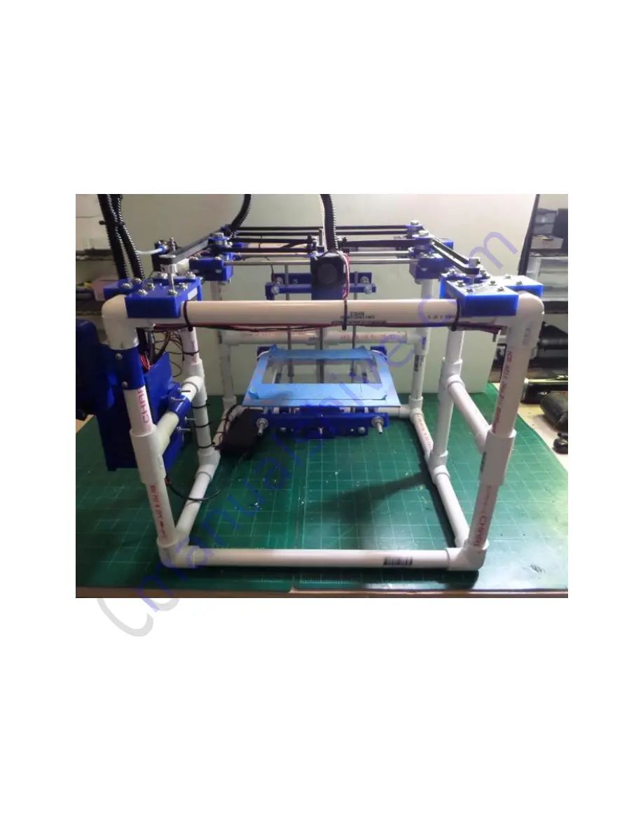
Страница 26: ...THE PVCore 3D PRINTER 12 28 2016 BY RCJOSEB PAGE 26 OF 107 FRAME ASSEMBLY FINAL This picture shows the completed frame as viewed from the front ...
Страница 27: ...THE PVCore 3D PRINTER 12 28 2016 BY RCJOSEB PAGE 27 OF 107 FRAME ASSEMBLY FINAL This picture shows the completed frame as viewed from the right ...
Страница 28: ...THE PVCore 3D PRINTER 12 28 2016 BY RCJOSEB PAGE 28 OF 107 FRAME ASSEMBLY FINAL This picture shows the completed frame as viewed from the left ...
Страница 29: ...THE PVCore 3D PRINTER 12 28 2016 BY RCJOSEB PAGE 29 OF 107 FRAME ASSEMBLY FINAL This picture shows the completed frame as viewed from the rear ...
Страница 30: ...e assembled with the following parts 02 x 3D printed motor mounts M1 02 x Nema 17 motors NM 02 x 20 Tooth x 5mm bore motor pulleys MP 04 x 6 x 1 5 Phillips pan head screws S1 5 04 x 6 x 2 0 Phillips pan head screws S2 0 24 x 6 Flat washers W6 08 x 6 Hex nuts N6 08 x M3 x 10mm cap head screws S10 0 ...
Страница 31: ...shown Attach the mounts M1 to the motors NM using four M3 x 10mm screws S10 0 and two washers W6 The M3 x 10mm screws S10 0 indicated by the yellow arrows are attached using Blue Loctite The other M3 x 10mm screws S10 0 are temporary so Blue Loctite and washers W6 are not needed The 20 Tooth x 5mm bore motor pulleys MP will be used later on during the build so set them aside ...
Страница 32: ...and washers W6 into the mount M1 and frame as shown From underneath insert a washer W6 and hex nut N6 onto each screw S2 0 Apply a small amount of Blue Loctite between the washer W6 and hex nut N6 Tighten the hex nut N6 using a wrench or socket but do not overtighten or the mount M1 may crack Repeat the above steps for the 1 5 screws S1 5 Repeat the above steps for the left side of the frame ...
Страница 33: ...x 3D printed bearing mounts B1 02 x 3D printed bearing supports B2 06 x 3D printed bearing spacers B3 02 x 5 16 x 2 0 hex bolts HB2 0 04 x 6 x 1 5 Philips pan head screws S1 5 04 x 6 x 2 0 Phillips pan head screws S2 0 02 x 5 16 flat washers W516 16 x 6 flat washers W6 02 x 5 16 hex nuts N516 08 x 6 hex nuts N6 04 x 6mm radial bearings 608ZZ ...
Страница 34: ...s a completed bearing assembly Place a 3D printed spacer B3 onto the bolt HB2 0 with center lip facing the end of the bolt HB2 0 Insert a 6mm radial bearing 608ZZ Insert a 3D printed spacer B3 with the center lip facing the head of the bolt HB2 0 Insert a 6mm radial bearing 608ZZ Insert a 3D printed spacer B3 with the center lip facing the head of the bolt HB2 0 Insert a 3D printed bearing support...
Страница 35: ...he bearing support B3 is seated firmly into the recessed hole in the bearing mount B1 Place a 5 16 washer W516 and 5 16 hex nut N516 onto the 5 16 hex bolt HB2 0 Apply a small amount of Blue Loctite to the 5 16 hex bolt HB2 0 and tighten the 5 16 hex nut N516 Verify that the radial bearings 608ZZ can spin freely and that the bearing assembly does not wobble ...
Страница 36: ...0 and washers W6 into the mount B1 and frame as shown From underneath insert a washer W6 and hex nut N6 onto each screw S2 0 Apply a small amount of Blue Loctite between the washer W6 and hex nut N6 Tighten the hex nut N6 using a wrench or socket but do not overtighten or the mount B1 may crack Repeat the above steps for the 1 5 screws S1 5 Repeat the above steps for the left side of the frame ...
Страница 37: ...axis slide Z2 02 x 0 25 x 12 threaded rods T0 25 02 x Metal LM6UU linear bearings LM6UU M or 3D printed LM6UU linear bearings LM6UU 3D 02 x 6mm x 12 smooth rods S6MM 02 x 5 16 hex nuts N516 04 x 6 x 0 5 Phillips pan head screws S0 5 12 x 0 25 flat washers W0 25 12 x 0 25 hex nuts N0 25 01 x 14 x 5 16 threaded rod T516 which is not shown in the picture ...
Страница 38: ...rinted Z axis slide Z2 Repeat the above steps for the other nut N516 that gets insert at the bottom of the Z axis slide Z2 Insert a 0 25 x 12 threaded rod T0 25 into one of the out holes in the 3D printed Z axis slide Z2 Leave 2 of the threaded rod T0 25 protruding out of the 3D printed Z axis slide Z2 Insert a 5 16 washer W516 and 5 16 nut N516 on opposite sides of the Z axis slide Z2 Place a sma...
Страница 39: ...n This helps to minimize the amount of binds Please note that linear bearings LM6UU M or LM6UU 3D travel along the length of the smooth rod while radial bearings 608ZZ ride around the smooth rod Select a linear bearing LM6UU M or LM6UU 3D and place it a polished and lubricated smooth rod S66M Move the linear bearing LM6UU M or LM6UU 3D back and forth along the length of the smooth rod S6MM If the ...
Страница 40: ...se note that the Z axis slide has a top and a bottom side even though they are not marked The bottom side is the one where the outer edge of the threaded rod T0 25 is closest to the outer edge of the Z axis slide Z2 Orient the Z axis slide Z2 so that the bottom is resting on the table Insert the linear bearing LM6UU M or LM6UU 3D all the way into the Z axis slide Z2 Tighten the 6 x 0 5 Phillips pa...
Страница 41: ...completed Z axis slide as if you were facing the front of the PVCore Place the corresponding smooth rod S6MM next to its married linear bearing LM6UU M or LM6UU 3D partner Label the smooth rod S6MM so that they can be identified easily later on in the build Set the Z axis slide aside for later ...
Страница 42: ... printed motor plate M3 01 x Nema 17 motor NM 01 x 5mm to 8mm flexible motor coupler MC 02 x 5 16 x 5 5 carriage bolts B516 04 x M3 x 10mm cap head screws S10 0 06 x 5 15 flat washers W516 06 x 5 16 hex nuts N516 02 x 6 x 0 5 Phillips pan head screws S0 5 02 x 6 x 1 5 Phillips pan head screws S1 5 06 x 6 flat washers W6 Please note eight are shown in picture but only six are needed ...
Страница 43: ...or coupler MC to the Nema 17 motor NM with Blue Loctite Attach the motor plate M3 to the motor mount M2 with two 6 washers W6 and two 6 x 1 5 screws S1 5 Thread the two carriage bolts B51 all the way through the motor mount M2 as shown Thread one 5 15 washer W516 and one 5 16 hex nut N516 onto each carriage bolt B516 Apply s small amount of Blue Loctite to the carriage bolt and tighten down the 5 ...
Страница 44: ...hat its bottom edge is closest to the table If not flip the guide Z1 180 degrees and re check Orient the completed motor mount assembly M2 as shown against the back of the 3D printer s PVC frame Ensure that the completed motor mount assembly M2 is centered when compared to the PVC frame Without moving the motor mount move the guides Z1 so that their holes are lined up with the threaded rods Use ta...
Страница 45: ...d Z axis top rod support Z3 02 x 3D printed Z axis frame supports Z4 01 x 6mm radial bearing 608ZZ 02 x 5 16 x 5 5 carriage bolts B516 02 x 6 x 1 5 Phillips pan head screws S1 5 02 x 6 x 0 5 Phillips pan head screws S0 5 02 x 6 x 1 0 Phillips pan head screws S1 0 06 x 5 16 flat washers W516 06 x 5 16 hex nuts N516 08 x 6 flat washers W6 04 x 6 hex nuts N6 ...
Страница 46: ...nd place a 3D printed Z axis frame support Z4 on the center pipe FV as shown Center the holes in the Z axis frame support Z4 with the T connector FT Using the Z axis frame support Z4 as a guide drill a 1 8 hole on one side of the pipe FV Place the PVC frame upright and drill another 1 8 on the opposite side of the pipe FV ...
Страница 47: ... using Blue Loctite Drill a 1 8 hole through the PVC pipe FV using the bottom hole in the Z axis frame support Z4 as a guide Insert a 6 x 1 5 Phillips pan head screw S1 5 6 washer W6 and 6 hex nut N6 on the bottom hole Tighten down the 6 hex nut N6 using Blue Loctite Insert 6 x 1 0 screws S1 0 6 washers W6 and 6 hex nuts N6 through the Z axis frame support Z4 Tighten down the 6 hex nuts N6 using B...
Страница 48: ...place Insert the 14 x 5 16 threaded rod T516 into the motor coupler MC but do not tighten the set screws Thread the Z axis slide Z2 onto the threaded rod T516 Ensure that the smooth rods S6MM engage the linear bearings LM6UU M or 3D in the Z axis slide Z2 Lower the slide until it s about two inches above the motor coupler MC Insert the Z axis top frame support Z3 onto the smooth rods S6MM and 5 16...
Страница 49: ...o use metal linear bearings LM6UU M which worked much better 02 x 11 x 6mm smooth rods S6MM 02 x 3D printed linear bearings LM6UU 3D or metal linear bearings LM6UU M 04 x 3D printed Y slide upper bodies Y1 04 x 3D printed Y slide lower bodies Y2 04 x 3D printed Y slide blocks Y3 06 x 3D printed bearing washers B3 02 x 3D printed bearing spacer B2 02 x 5 16 x 2 5 hex head bolt HB2 5 04 x 608ZZ radi...
Страница 50: ...ting the 6mm radial bearings 608ZZ from binding The picture shows a completed bearing assembly Place a 3D printed spacer B3 onto the bolt HB2 0 with center lip facing the end of the bolt HB2 5 Insert a 6mm radial bearing 608ZZ Insert a 3D printed spacer B3 with the center lip facing the head of the bolt HB2 0 Insert a 6mm radial bearing 608ZZ Insert a 3D printed spacer B3 with the center lip facin...
Страница 51: ...mooth rod S6mm Place the 3D printed linear bearing LM6UU 3D between the upper and lower Y slides bodies Y1 and Y2 Place one 3D printed Y slide block Y3 on top of the Y slide body Y2 while aligning the cutouts Thread a 6 flat washer W6 onto a 6 x 2 0 Phillips pan head screw S2 0 and insert into the block Y3 Thread a 6 washer W6 and a 6 hex nut N6 at the other end and hand tighten without Blue Locti...
Страница 52: ... axis slide is assembled with the following parts 02 x 12 x 6mm smooth rods S6mm 02 x 3D printed linear bearings LM6UU 3D or metal linear bearings LM6UU M 01 x fully assembled hotend HE 04 x 3D printed standoffs X1 02 x 3D printed X slide bodies X2 01 x 3D printed hotend base X3 01 x 3D printed hotend clamp X4 04 x 3D printed GT2 belt clips X5 OPTIONAL 04 x 6 x 2 0 Phillips pan head screws S2 0 04...
Страница 53: ...into the hotend base X3 with the wires exiting the hotend to the right Attach the hotend clamp X4 to the hotend base X3 using 1 0 screws S1 0 6 washers W6 and 6 hex nuts N6 Tighten down the hex nuts N6 without using any Blue Loctite The hotend HE should be held in place firmly so that it does not wiggle ...
Страница 54: ...e halves X2 using four 1 5 screws S1 5 eight 6 washers W6 and four hex nuts N6 Do not fully tighten down the hex nuts N6 Insert the 3D printed linear bearings LM6UU 3D so that they are flush with the left side of the X slide body X2 Apply a small amount of Blue Loctite to the screws S1 5 and tighten the hex nuts N6 Ensure that there are no binds by moving the smooth rods S6MM back and forth ...
Страница 55: ...head of the screw The distance can be measured manually with a ruler or by using something that is already 5 8 in length I used 1 8 diameter shrink wrap tubing and cut it to the proper length Place a small amount of Blue Loctite onto the 2 0 screw S2 0 where the 6 hex nut N6 will be Thread the 6 hex nut N6 so that it is 5 8 inches away from the pan head Let the Blue Loctite fully set Repeat the ab...
Страница 56: ... from occurring I installed 5 16 washers W516 between the two X slide halves X2 on each side This is optional as you may not have this issue Partially insert the screws S2 0 from the previous step into the top of the X slide body X2 with 6 washers W6 Insert the 3D printed spacers X1 onto the screws from the other side of the X slide X2 Fully insert the screws S2 0 and place a 6 washer W6 and a 6 h...
Страница 57: ...e assembled with the following parts Please note that the picture does not show all of the quantities for each part Actual quantities are listed below 04 x 3D printed Y axis rod holders Y4 04 x 6 x 0 75 Phillips pan head screws S0 75 04 x 6 hex nuts N6 20 x 6 flat washers W6 04 x M3 x 10mm cap head screws S10 ...
Страница 58: ...yellow arrows Place a Y rod holder Y4 on each end of a 6mm smooth rod S6MM that is being used for the Y axis Place the front Y rod holder Y4 onto the motor mount M1 Place the rear Y rod holder Y4 onto the bearing mount B1 Replace the M3 x 5mm S5 screws with M3 x 10mm cap head screws S10 and three 6 washers W6 Insert the 6 x 0 75 screws S0 75 6 washers W6 and 6 hex nuts N6 on the rear Y rod holder ...
Страница 59: ...he Y slides Y1 2 Center each smooth rod S6mm so it s evenly spaced between the Y slides T1 2 Re install the Y slide blocks Y3 that were previously removed This picture shows the completed X axis Test the X and Y slides for binding and loosen screws where necessary to obtain smooth movement It may help to lubricate the smooth rods S6MM with oil or silicone spray ...
Страница 60: ...C pipe frame Tighten down the hex nut N516 on each side of the hex bolt B516 towards the PVC frame Using a bubble level position the Z axis top plate Z2 so that the Z axis is vertically level Place a small amount of Blue Loctite on the hex bolt B516 on each side of the PVC pipe frame Tighten down the hex nut N516 on each side of the hex bolt B516 towards the PVC frame Re check for level and make a...
Страница 61: ... 12 28 2016 BY RCJOSEB PAGE 61 OF 107 GT2 MOTOR PULLEY AND BELTS PARTS To connect the X Y axis to the motors the following parts are needed 02 x 5 x 6mm GT2 belts GT2 5 02 x 5mm bore 20T Motor Pulleys MP 04 08 x 6 Zip ties ...
Страница 62: ...unt s lower bearing Goes around the left bearing mount s lower bearing Goes around the left Y slide s lower bearing Stops at the left front corner of the X axis slide Place the motor pulleys MP onto the motors but do not tighten the set screws Prevent the X Axis slide from moving away from the right front corner of the PVCore by using either tape or string Start with the upper belt first with the ...
Страница 63: ...THE PVCore 3D PRINTER 12 28 2016 BY RCJOSEB PAGE 63 OF 107 GT2 MOTOR PULLEY AND BELTS INSTALLATION ...
Страница 64: ...THE PVCore 3D PRINTER 12 28 2016 BY RCJOSEB PAGE 64 OF 107 GT2 MOTOR PULLEY AND BELTS INSTALLATION Here is a close up picture of the GT2 belts at the X Axis slide ...
Страница 65: ...THE PVCore 3D PRINTER 12 28 2016 BY RCJOSEB PAGE 65 OF 107 GT2 MOTOR PULLEY AND BELTS INSTALLATION Here is a close up pictures of the GT2 belts on the right side of the PVCore ...
Страница 66: ...THE PVCore 3D PRINTER 12 28 2016 BY RCJOSEB PAGE 66 OF 107 GT2 MOTOR PULLEY AND BELTS INSTALLATION Here is a close up picture of the GT2 belts on the left side of the PVCore ...
Страница 67: ... 67 OF 107 Y AXIS ENDSTOP SWITCH MOUNT PARTS The Y Axis Endstop Switch is assembled with the following parts 01 x PCB Endstop Switch ESY1 01 x 1 8 foam ESY2 01 x 3D printed Y Axis Endstop Switch Mount ESY3 03 x 4 zip ties SZT 01 x 6 zip tie not shown ...
Страница 68: ... endstop Place the 3D printed Y Axis Endstop Switch Mount ESY3 onto the right Y Axis smooth rod S6MM as shown Place the 1 8 foam ESY2 underneath the mount and use a scissor to poke holes through the foam Place the PCB Endstop Switch ESY1 underneath the foam ESY2 and align the holes Use the 4 zip ties to hold the three parts together Ensure the heads on the zip ties are below the endstop Place anot...
Страница 69: ...THE PVCore 3D PRINTER 12 28 2016 BY RCJOSEB PAGE 69 OF 107 Y AXIS ENDSTOP SWITCH MOUNT INSTALLATION This picture shows where the X Axis slide engages the switch ...
Страница 70: ... Axis Endstop Switch is assembled with the following parts 01 x PCB Endstop Switch ESX1 01 x 3D printed X Endstop Switch Trigger ESX2 02 x 3D printed X Endstop Switch Supports ESX3 02 x 6 flat washers W6 02 x 6 hex nuts N6 01 x 6 x 1 25 Phillips Pan Head Screw 01 x 6 x 2 0 Phillips Pan Head Screw ...
Страница 71: ...hat the 3D printed X Endstop Switch Trigger ESX2 cannot move back and forth Insert the screw S1 25 into the left hole of the PCB Endstop Switch ESX1 Insert the screw S2 0 into the right hole of the PCB Endstop Switch ESX1 Thread the 3D printed X Endstop Switch Supports ESX3 onto the other side of the screws Insert the screws into the Y Axis Slide and secure them using the 6 washers W6 and 6 hex nu...
Страница 72: ...BOM The print bed is a piece of window glass that you can purchase and have cut to size at your favorite hardware store I had a piece of glass at home so I cut it to size myself I placed some blue tape around the edges to prevent cuts The width is 8 25 The length is 8 25 ...
Страница 73: ... lower bed support PB2 2 x 3D printed rear lower bed supports PB3 2 x 3D printed rear upper bed supports PB4 1 x 3D printed front upper bed support PB5 3 x 8 x 1 5 screws S8 Two are shown installed 3 x 8 wing nuts WN8 3 x 0 275 x 1 5 springs SP1 Please note that the following parts are from the Z Axis Slide Assembly 2 x 0 25 x 12 threaded rods T0 25 16 x 0 25 hex nuts N0 25 16 x 0 25 flat washers ...
Страница 74: ...ove Please note that the picture does not show all of the required hex nuts and washers The arrows point to the location of where a hex nut N0 25 and washer W0 26 should be added Leave all hex nuts N0 25 loose The 3D printed rear lower bed supports PB3 should face away from each other The remaining four flat washers E0 25 and hex nuts B0 25 will be installed later ...
Страница 75: ... in far enough without touching the PVC frame 3 Use Blue Loctite and tighten down the 0 25 hex nuts N0 25 towards each other 4 Assemble the 3D printed rear upper print bed supports PB4 o Thread a 8 screw S8 into the support PB4 o Insert a spring SP1 on the opposite side of the support PB4 o Insert the support PB4 onto the lower printed bed support PB3 o Thread a 8 wing nut WN8 onto the 8 screw S8 ...
Страница 76: ...vertighten it as it will then cause the print bed support to angle upwards 1 Ensure the 0 25 hex nut N0 25 is not tight up against the print bed support 2 Use Blue Loctite and tighten down the 0 25 hex nut N0 25 up against the print bed support 3 Use Blue Loctite and tighten down the 0 25 hex nut N0 25 up against the print bed support 4 Assemble the front print bed support in the same manner that ...
Страница 77: ...THE PVCore 3D PRINTER 12 28 2016 BY RCJOSEB PAGE 77 OF 107 PRINT BED SUPPORTS ASSEMBLY This the view of the almost completed print bed support from the front ...
Страница 78: ...THE PVCore 3D PRINTER 12 28 2016 BY RCJOSEB PAGE 78 OF 107 PRINT BED SUPPORTS ASSEMBLY This the view of the almost completed print bed support from the top ...
Страница 79: ...THE PVCore 3D PRINTER 12 28 2016 BY RCJOSEB PAGE 79 OF 107 PRINT BED SUPPORTS ASSEMBLY This the view of the almost completed print bed support from the top ...
Страница 80: ...THE PVCore 3D PRINTER 12 28 2016 BY RCJOSEB PAGE 80 OF 107 PRINT BED SUPPORTS ASSEMBLY Place the glass bed onto the upper print bed supports ...
Страница 81: ... ASSEMBLY As before the 0 25 hex nuts labeled 2 will be used as opposing nuts 1 Move the lower print bed support back and forth so that the upper print bed support is up against the glass bed 2 Use Blue Loctite and tighten the 0 25 hex nuts up against the lower print bed support ...
Страница 82: ...THE PVCore 3D PRINTER 12 28 2016 BY RCJOSEB PAGE 82 OF 107 PRINT BED SUPPORTS ASSEMBLY Here is a picture showing the completed print bed ...
Страница 83: ...8 2016 BY RCJOSEB PAGE 83 OF 107 Z AXIS END STOP SWITCH BOM The Z Axis Endstop Switch is assembled with the following parts 1 X PCB Endstop Switch ZES 1 x 3D Print Endstop Switch Mount ZM 1 x Small piece of double sided tape ZT ...
Страница 84: ...THE PVCore 3D PRINTER 12 28 2016 BY RCJOSEB PAGE 84 OF 107 Z AXIS END STOP SWITCH ASSEMBLY Tighten the thumb screws on the print supports all the way down so the glass print bed is lowered ...
Страница 85: ...idth as the mount ZM Remove one side of the backing on the double sided tape ZT Fold the double sided tape ZT over the top edge of the endstop switch ZES Remove the other side of the backing from the double sided tape ZT Insert the endstop switch ZES all the way into the slot of the switch mount ZM Press the endstop switch ZES firmly into the mount ZM ...
Страница 86: ...F 107 Z AXIS END STOP SWITCH ASSEMBLY Mount the endstop switch assembly onto the Z Axis top plate It should hold just by pressure butt if it feels loose then attach using double sided tape or glue Raise the print bed until the endstop switch is activated ...
Страница 87: ...ER 12 28 2016 BY RCJOSEB PAGE 87 OF 107 Z AXIS END STOP SWITCH ASSEMBLY There should be a gap about 3mm 5mm between the glass print bed and the print head nozzle This gap will be adjusted during the bed leveling procedure ...
Страница 88: ...d RAMPS case front RCF 1 x 3D printed RAMPS case top RCT 1 x 3D printed RAMPS case bottom RCB 1 x 3D printed RAMPS case left side RCL 1 x 3D printed RAMPS case right side RCR 1 x 3D printed RAMPS case mount RCM 4 x 3D printed RAMPS case standoffs RCS 4 x 6 x 1 25 Philips pan had screws S1 25 or 4 x 6 x 1 00 Philips pan had screws S1 00 4 x 6 flat washers W6 4 x 6 hex nuts N6 ...
Страница 89: ...ottom RCB on the left side of the frame with the large cutout facing down Thread 4 x 6 Phillips head screws through the case bottom Thread 4 x 3D printed standoffs onto the screws Attach the 3D printed case mount Thread 4 x 6 flat washers and hex nuts Hand tighten down the hex nuts without Blue Loctite ...
Страница 90: ...THE PVCore 3D PRINTER 12 28 2016 BY RCJOSEB PAGE 90 OF 107 RAMPS CASE ASSEMBLY Place strips of double sides tape onto the case bottom so that the strips cover the screw heads ...
Страница 91: ...THE PVCore 3D PRINTER 12 28 2016 BY RCJOSEB PAGE 91 OF 107 RAMPS CASE ASSEMBLY Place the RAMPS board into place and rotate the case and RAMPS so that they are horizontal ...
Страница 92: ... 92 OF 107 RAMPS CASE ASSEMBLY It is better to connect the power cables now rather than after assembling the case Connect the Hot end wires Connect a JST connector for the filament fan Connect the power supply cables and an on off switch if using one ...
Страница 93: ...F 107 RAMPS CASE ASSEMBLY Place the case front cover into position and tidy up the cables To keep the cover in place place a bead of hot glue along the edge where it meets the bottom of the case Glue the remaining case parts in place except for the cover ...
Страница 94: ...THE PVCore 3D PRINTER 12 28 2016 BY RCJOSEB PAGE 94 OF 107 RAMPS CASE ASSEMBLY Here is the completed case in its proper position The case fan will be installed later ...
Страница 95: ...PRINTER 12 28 2016 BY RCJOSEB PAGE 95 OF 107 RAMPS CASE ASSEMBLY This is a top view of the case The larger cutout is for all of the cables except for the LCD display cables which are passed through the smaller cutout ...
Страница 96: ...THE PVCore 3D PRINTER 12 28 2016 BY RCJOSEB PAGE 96 OF 107 FILAMENT FAN BOM The filament fan is assembled with the following parts 1 x 40mm fan FFAN40 1 x Fan mount FFM 8 x 4 zip ties SZT ...
Страница 97: ...TER 12 28 2016 BY RCJOSEB PAGE 97 OF 107 FILAMENT FAN ASSEMBLY Use a 1 8 drill bit to clean out the four fan mounting holes Do not drill all the way through the mount Insert a 4 zip tie through each hole from underneath ...
Страница 98: ...Y RCJOSEB PAGE 98 OF 107 FILAMENT FAN ASSEMBLY Place the fan onto the mount with a zip tie through each mounting hole Place another zip tie onto the existing one and tighten down the zip tie heads against each other Trim off the excess ...
Страница 99: ... 2016 BY RCJOSEB PAGE 99 OF 107 FILAMENT FAN ASSEMBLY Loosen and remove the two existing screws from the X carriage Place the fan mount into position Re insert the screws Thread and tighten down the nuts Zip tie any loose cables ...
Страница 100: ...se to remove them and support the extruder motor with a mount that supports the entire motor The Thingiverse article lists the hardware needed to assemble the extruder The extruder mount is assembled with the following parts 1 x Completed extruder motor and extruder 1 x Extruder mount 1 x Bowden tube 1 x Pneumatic Fitting 2 x 6 32 x 1 25 Pan Head Screws 2 x 6 washers 2 x 6 32 Hex Nuts ...
Страница 101: ...THE PVCore 3D PRINTER 12 28 2016 BY RCJOSEB PAGE 101 OF 107 EXTRUDER MOTOR MOUNT ASSEMBLY Use the drill template to drill 1 8 or larger diameter holes where shown Dry fit the screws to ensure they fit ...
Страница 102: ...THE PVCore 3D PRINTER 12 28 2016 BY RCJOSEB PAGE 102 OF 107 EXTRUDER MOTOR MOUNT ASSEMBLY Drop the extruder motor in place ...
Страница 103: ...THE PVCore 3D PRINTER 12 28 2016 BY RCJOSEB PAGE 103 OF 107 EXTRUDER MOTOR MOUNT ASSEMBLY Connect the Pneumatic fitting to the extruder Connect the Bowden tube from the extruder to the hot end ...
Страница 104: ... 12 28 2016 BY RCJOSEB PAGE 104 OF 107 LCD CASE BOM The LCD case is assembled with the following parts Modified LCD case bottom LCD case front LCD Case button 2 x 6 32 x 1 25 Pan Head Screws 2 x 6 washers 2 x 6 32 Hex Nuts ...
Страница 105: ...16 BY RCJOSEB PAGE 105 OF 107 LCD CASE ASSEMBLY Attach the modified LCD case bottom to the front left side of the PVC core using the screws as before Install the LCD screen and button Hold the case together using zip ties or screws ...
Страница 106: ... OF 107 CABLE CONNECTIONS AND CABLE ROUTING I am not going to explain how to wire up the printer in this guide because electronics vary so follow the manufacturer s instructions I suggest using zip ties to route the cables neatly throughout the PVC frame ...
Страница 107: ...THE PVCore 3D PRINTER 12 28 2016 BY RCJOSEB PAGE 107 OF 107 THE END ...