26
| Calibration
26.4 Installing the PPM receiver
The PPM receiver uses PPM technology. Do not confuse
PPM (Pulse-position modulation) and PWM (Pulse-width
modulation).
Study the manufacturer’s instructions supplied with the
PPM receiver and pay special attention to information/
instructions on pin allocation.
WARNING! Your PPM receiver may feature wire antennas
to improve reception. DO NEVER let the wire antennas touch
any PCB board, carbon fibre part, electrical component or
metal component. The electronic system may immediately
be destroyed!
NEVER install a PPM receiver inside the canopy!
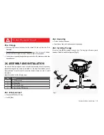
1.
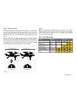
Study the installation diagrams in
[ Fig. 6 ]
.
2.
Turn the »NovaX 350 upside down and place it on a soft and stable surface
[1]
.
3. Loosen and remove the four nuts that hold the camera platform in place and remove
the platform
[2]
.
4. Cut a double-faced adhesive foam pad that is half the width of and as long as the
receiver. Align and stick the foam pad along the left edge of the receiver underside.
With the header pins facing up, stick the receiver on the »NovaX 350’s underside.
Connect the PPM and telemetry cable to the corresponding header pins on the
receiver.
[3]
.
5. Replace the camera platform and tighten the nuts
[4]
.
6.
Affix one antenna on each boom
[6]
. Pay attention to these points:
»
Place the antennas at a 90° angle to each other. See
[5]
.
»
Antennas must not touch.
»
Keep antennas as straight as possible.
»
Keep antennas away from noise (motor or speed controller).
»
A bare antenna wire must never touch conductive (metal and carbon fibre)
parts of the »NovaX 350. A minimum distance of 15 mm is required between
conductive materials and a bare antenna wire.
27. CALIBRATION
Make sure you read through the entire calibration chapter
before you start calibrating the
»NovaX 350.
If you fly the »NovaX 350 for the first time it is necessary to
calibrate it prior to the first take-off.
Remove the propellers before you proceed!
Only after you have successfully completed the calibration
mount the propellers again.
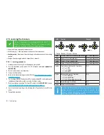
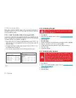
Calibration is divided into the following steps:
Step
Chapter
1
27.4 Binding transmitter and receiver
2
27.5 Learning the channels
3
27.6 Calibrating the gyro
4
27.7 Calibrating the compass
5
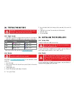
28. Testing the motors
6
29. Installing the propellers
Содержание NovaX 350
Страница 1: ...88012RC ArF 88014RC RtF NovaX 350 Operating instructions M1...
Страница 2: ...2 EVER WONDERED WHAT INNOVATION LOOKS LIKE NovaX 350...
Страница 20: ...20 Dimensions 22 DIMENSIONS 22 1 Short legs 283 mm 283 mm 250 mm 169 mm 58 mm 2 0 3 m m 3 4 7 m m...
Страница 21: ...Dimensions 21 22 2 Long legs 283 mm 283 mm 250 mm 241 mm 130 mm 2 0 3 m m 3 4 7 m m...
Страница 27: ...Calibration 27 2 1 90 90 90 1 2 3 4 5 6 Fig 6...
Страница 49: ...49...
Страница 50: ...50...
Страница 51: ...51...
Страница 52: ...52 www rclogger com...


