Raypak Raypak Delta Limited WH1-399B Скачать руководство пользователя страница 24

24

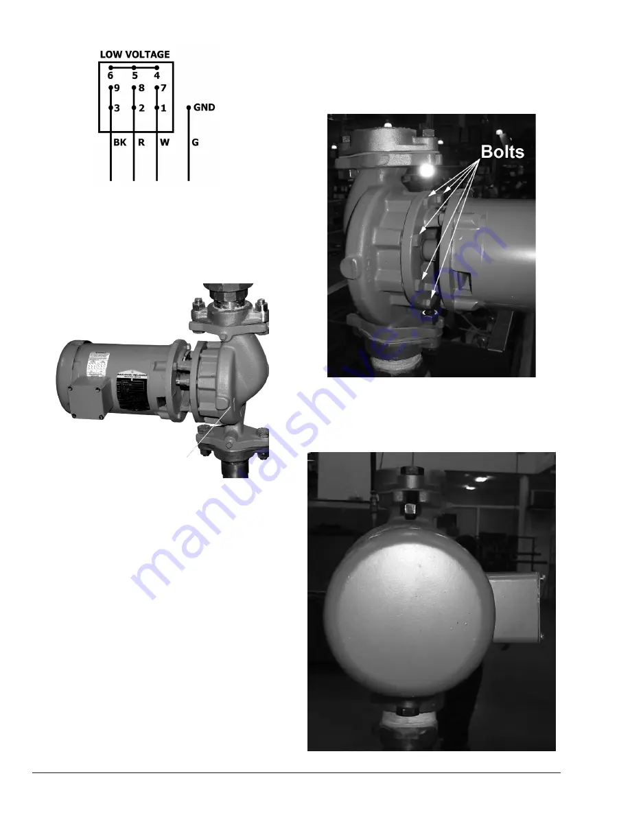
Figure 25.  Cold Water Run Control Panel and Injector 

Pump Wiring

11.  Turn heater on to receive a “call-for-heat” and verify 

the injector pump is rotating in the proper direction 

(clockwise). The pump volute has an arrow cast into 

the housing indicating the proper rotational direction. 

See 

Figure 26

.

DIRECTIONAL ARROW

Figure 26.  Directional Arrow

12. If the pump is rotating in the proper direction, secure 

the heater from installation.

13. If the pump is rotating incorrectly, turn off power and 

swap  ONLY  two  of  the  line  voltage  leads  into  the 

pump (for example, swap the red and black leads). 

Confirm  that  the  pump  now  rotates  in  the  proper 

direction before proceeding.

14. Secure from installation.

Injection Pump Cover Installation

 (Required for Outdoor Installation Only)

Before Starting

1.  Turn off power to the unit at the circuit breaker.
2.  Turn off gas supply.
3.  Shut-off  the  water  supply  to  the  heater  and,  if 

necessary, drain water from the system.

4.  Allow heater to cool down before attempting work.

In order to install the pump cover, you will need to rotate the 

pump body so that the electrical box is pointing downward, 

as outlined in the following steps:
1.  Loosen and remove the eight (8) 9/16" bolts holding 

the pump body in place. See 

Figure 27

.

Figure 27.  Remove the eight bolts holding the pump body 

in place

2.  Remove  the  pump  body  then  rotate  it  so  that  the 

electrical box is pointing downward, ensuring not to 

damage the seal. See 

Figure 28

 through 

Figure 30

.

Figure 28.  Remove the pump body

Содержание Raypak Delta Limited WH1-399B

Страница 1: ...ndividuals specially trained and experienced in the installation and maintenance of this type of equipment and related system components Installation and service personnel are required by some states to be licensed Persons not qualified shall not attempt to install service or maintain this equipment This manual should be maintained in legible condition and kept adjacent to the variable speed pump ...

Страница 2: ...d Water Start on page 5 Caution revised on page 5 Revised first note on page 9 Figure 12 revised on page 9 Caution revised on page 9 Figure 21 revised on page 21 Obsolete text and figures relating to Elodrive removed Obsolete text and figures related to Hitachi Inverters removed Illustrated Parts List section added on page 32 ...

Страница 3: ...Boxes 16 Installing the Temperature Sensor 16 Installing the Three way Valve 16 Connecting Power to the Controller 16 Connecting the CWS Control to the Multi Boiler Interlock Box 16 Connecting the Boiler to the CWS Multi Boiler Interlock 16 Actuator to Valve Orientation 16 Three Way Valve Ball Orientation 17 Valve Installation 17 4 Inch Valve Orientation 17 Connecting the Actuator 18 Typical Cold ...

Страница 4: ...azardous condition which could cause minor personal injury or product or property damage if ignored NOTE Indicates special instructions on installation operation or maintenance which are important but not related to personal injury hazards NOTE Minimum 18 AWG 105 C stranded wire must be used for all low voltage less than 30 volts external connections to the unit Solid conductors should not be used...

Страница 5: ...alves are available see manual Time Temperature Relationships in Scalds The following chart details the relationship of water temperature and time with regard to scald injury and may be used as a guide in determining the safest water temperature for your applications Water Temp Time to Produce Serious Burns 120ºF 48 9 C More than 5 Minutes 125ºF 51 7 C 1 1 2 to 2 Minutes 130ºF 54 4 C About 30 Seco...

Страница 6: ...els locating dimples are provided for ease of drilling the mounting holes You will need to drill mounting holes through the heater side panel for the routing of wiring and the sensor Figure 3 Multi meter Installing the Temperature Sensor Avoid routing wiring on or near other electrical wires conduit motors spark igniters or other sources of high intermittent voltage or current The sensor should be...

Страница 7: ...27 mm 1 5 16ʺ 34 mm 6 5 8ʺ 168 mm LEFT SIDE CONTROL BOX MTG PANEL 11 16 17 mm 7 1 4 184 mm 11 1 8 283 mm Figure 5 Component Locations Raytherm Models 514 824 11 1 8 283 mm 10 5 16 262 mm CONTROL BOX MTG PANEL 1 51 mm Figure 6 Component Locations Raytherm Models 926 1826 CONTROL BOX MTG PANEL 22 559 mm 7 5 8 194 mm 1 1 2 38 mm Figure 7 Component Locations Raytherm Models 2100 4001 ...

Страница 8: ... the following upon a CALL FOR HEAT signal from the heater 1 CALL FOR HEAT LED on PCB illuminates GREEN 2 START UP MODE LED on PCB illuminates YELLOW It should go out in less than 7 minutes as the boiler inlet temperature approaches the setpoint temperature 3 The ACTUATOR should be in the fully open position or move to the fully open position if not already there Actuator and ball rotated to the a...

Страница 9: ...l is energized and closes the contacts allowing 24VAC to energize the CFH terminal on the cold start circuit board a A two second delay occurs from the CFH signal to the output of power from terminal MC of the cold start circuit board 11 24VAC is sent from terminal 2 of terminal block 3 to the NO contacts of the DPST relay located in the cold start control panel 12 After the two second delay on th...

Страница 10: ...ounting the actuator to the valve ensure that the valve stem is oriented with the machined flat notch positioned parallel to the A and AB ports as shown in Figure 13 All actuators used by Raypak include the spring return safety feature This means that upon loss of power during operation the valve automatically rotates back to the full system flow position avoiding high limit lockouts or other issu...

Страница 11: ...low tab labeled High Pressure see Figure 17 This is for maintenance of the valve only If the valve stem begins leaking beneath the yellow tab the internal packing material must be replaced The High Pressure tab is held on with two screws located under the mounting bracket To replace the packing material all water pressure must be removed from the valve assembly and the assembly must be isolated fr...

Страница 12: ...f cold start controller have 120 VAC Heater is in standby mode Correct wiring to match wiring diagram YES NO NO YES YES NO NO NO YES YES NO The unit is okay YES NO YES Correct wiring Is the actuator modulating after 2 1 2 minutes NO Correct wiring YES Is the heater tripping the high limit YES NO Verify actuator is set to reverse acting and three way valve is not installed backwards 2 2 1 2 valve m...

Страница 13: ...Y CLOSED POSITION 3 PIPE ALL RELIEF VALVES TO DRAIN OR AS LOCAL CODES REQUIRE 4 BUFFER TANK REQUIRED WHEN WATER VOLUME IN BOILER LOOP IS NOT ADEQUATE TO PROVIDE STABLE TEMPERATURE CONTROL CONSULT FACTORY FOR TANK SIZING 5 SYSTEM FLOW MUST EXCEED HEATER FLOW AT ALL TIMES Typical Cold Water Start Piping ...

Страница 14: ...14 Wiring Diagrams Cold Water Start ...

Страница 15: ...15 HEATER INTERFACE WIRING FOR CWS OR CWR CWS CWR CONTROL OR MULTIPLE BOILER INTERFACE CWS CWR CONTROL OR MULTIPLE BOILER INTERFACE CWS CWR CONTROL OR MULTIPLE BOILER INTERFACE Heater Interface Wiring ...

Страница 16: ...re 9 for detailed instruction Connecting the CWS Control to the Multi Boiler Interlock Box Installer to provide four 18AWG stranded wires between pins 7 10 on the Cold Start Control and 7 10 on the Multi Boiler Interlock as shown in Wiring Diagram on page 19 Do not use solid core wire when wiring any portion of the Cold Start Multi Boiler system Connecting the Boiler to the CWS Multi Boiler Interl...

Страница 17: ... into your piping system in accordance with this manual Valve Installation To properly install this valve port AB must be connected to the combined outlet of the heater s and port B must be attached to the bypass between the combined inlet and the combined outlet as shown on page 18 The valve body has the port designators cast into the drive linkage housing See Figure 19 PORT AB Figure 19 Valve Or...

Страница 18: ...AS LOCAL CODES REQUIRE 3 LOCATE UNIONS TO FACILITATE SERVICING OF PLUMBING SIDE 4 BUFFER TANKS MAY BE REQUIRED TO PROVIDE STABLE TEMPERATURE CONTROL ON SYSTEMS WITH VARIABLE FLOW OR LOW WATER VOLUME CONSULT FACTORY FOR SELECTION CRITERIA 5 MAXIMUM 4 TIMES THE PIPE DIAMETER OR 12 WHICHEVER IS LESS 6 SYSTEM FLOW MUST EXCEED HEATER FLOW AT ALL TIMES ...

Страница 19: ...19 CWS CONTROL BOX ASSY SEE PAGE 16 FOR HEATER INTERFACE WIRING SEE PAGE 17 Wiring Diagram Multiple Boiler ...

Страница 20: ...ed to provide Installation Codes Installations must be in accordance with local state provincial and national codes laws regulations and ordinances In the absence of local codes installations must be in accordance with the latest editions of the National Fuel Gas Code ANSI Z223 1 NFPA 54 National Electrical Code ANSI NFPA 70 For Canada only CAN CSA B149 Installation Code and CSA C22 1 C E C Part 1...

Страница 21: ...C 120 454 3 25 13 9 13 38 8 1632 5 6 68 257 4 45 25 0 1911 1 3 2002C 132 499 7 26 14 4 19 56 8 1634 6 1 74 280 1 46 25 6 1935 3 4 2072C 132 499 7 27 15 0 19 56 8 1634 6 1 75 283 9 47 26 1 1935 3 4 2342C 132 499 7 30 16 7 21 4 63 9 1634 6 1 80 302 8 50 27 8 1935 3 4 Table C Injector and Heater Pump Specifications Hi Delta Heater Model Heater Pump Injector Pump Flow GPM lpm Temp Rise ºF ºC Press Dro...

Страница 22: ...36 90 340 7 25 13 9 13 2 39 4 1630 4 7 60 227 1 37 20 6 1911 1 3 1414 1468 90 340 7 27 15 0 14 0 41 8 1632 5 65 60 227 1 40 22 2 1911 1 3 1571 1631 90 340 7 30 16 7 14 5 43 3 1632 5 65 60 227 1 45 77 0 1911 1 3 1758 1826 90 340 7 34 18 9 15 4 46 0 1632 5 65 60 227 1 50 27 8 1911 1 3 2100 172 651 1 20 11 1 11 0 32 9 1641 6 9 130 492 1 26 14 4 1935 3 4 2500 200 757 1 21 11 7 15 8 47 2 1641 6 9 130 4...

Страница 23: ...shown in Figure 24 5 Remove the pump junction box cover shown in Figure 24 and locate the 9 wires inside DECAL COVER Figure 24 Pump Wiring Decal and Junction Box 6 Wire in accordance with the low voltage 230VAC decal located next to the pump junction box do not connect high voltage 460 volt power to the control box 7 In the absence of the pump mounted decal use Table F to complete the wiring betwe...

Страница 24: ...on before proceeding 14 Secure from installation Injection Pump Cover Installation Required for Outdoor Installation Only Before Starting 1 Turn off power to the unit at the circuit breaker 2 Turn off gas supply 3 Shut off the water supply to the heater and if necessary drain water from the system 4 Allow heater to cool down before attempting work In order to install the pump cover you will need t...

Страница 25: ...re 30 Reposition the pump body so that the electrical box points downward 3 Insert and tighten all eight 8 bolts securing the pump body in place 4 You will now be able to install the pump cover See Figure 31 and Figure 32 Figure 31 Place the cover on the pump Figure 32 Pump cover angle view ...

Страница 26: ... ALL RELIEF VALVES TO DRAIN OR AS LOCAL CODES REQUIRE 4 SYSTEM FLOW MUST EXCEED HEATER FLOW AT ALL TIMES Typical Cold Water Run Piping Pool Apps SEE NOTE 4 NOTES 1 LOCATE UNIONS TO FACILITATE SERVICING OF PLUMBING SIDE 2 PLUMB SWING CHECK VALVE IN GRAVITY CLOSED POSITION 3 PIPE ALL RELIEF VALVES TO DRAIN OR AS LOCAL CODES REQUIRE 4 USE REDUCING TEES WHERE INDICATED 5 SYSTEM FLOW MUST EXCEED HEATER...

Страница 27: ...cold run circuit board pin MC outputs a 24VAC signal to terminal AL0 of the Hitachi inverter 8 The AL0 relay closes and outputs a 24VAC signal to the coil of the DPST relay located in the cold run control panel 9 The DPST relay coil energizes and closes the NO contacts 10 Once the NO contacts of the DPSTclose the heater 24VAC is sent back to the heater to complete the circuit pin 3 of terminal blo...

Страница 28: ...ve 120VAC or 230VAC Heater is in standby mode Correct Wiring YES NO NO YES YES NO NO NO YES YES NO The unit is okay YES NO YES Correct wiring Is the injector pump modulating after 2 1 2 minutes NO Correct wiring YES Is the heater tripping the high limit YES NO Verify pump is rotating in proper direction Pump must decrease RPM s on decreasing 0 10VDC signal YES Correct 3 phase pump wiring NO Is 24V...

Страница 29: ...29 Wiring Diagrams Cold Water Run SEE PAGE 17 ...

Страница 30: ...y part returned for replacement under standard company warranties must be properly tagged with RAYPAK return parts tag completely filled in with the heater serial number model number etc and shipped to the Company freight prepaid If determined defective by the Company and within warranty the part will be returned in kind or equal substitution freight collect Credit will not be issued RAYPAK INC 21...

Страница 31: ...31 7 ILLUSTRATED PARTS LISTS Cold Water Start Manufactured from 2006 through current ...

Страница 32: ...32 1 M 8 M Cold Water Start ...

Страница 33: ...33 Cold Water Start Multiple Boiler Interlock ...

Страница 34: ...34 NOTE Sizing is specific to the application ...

Страница 35: ...35 4 C 1 S 1 S 1 S 1 S 1 C 5 C 2 C 3 C 7 C 9 C 10 C 10 C 4 S 8 C 3 S MVB MODELS ONLY 2 S 7 C Cold Water Run Manufactured 2006 thru current except 302B and 402B thru 5 31 2015 ...

Страница 36: ...36 9 M 4 M RAYTHERM MODELS 2100 4001 ONLY 1 H 5 M 6 M 7 M 8 M 10 M 12 M 11 M 4 M 2 M 1 M Cold Water Run ...

Страница 37: ...37 NOTE Sizing is specific to the application ...

Страница 38: ...38 NOTES ...

Страница 39: ...39 NOTES ...

Страница 40: ...Raypak Inc 2151 Eastman Avenue Oxnard CA 93030 805 278 5300 Fax 805 278 5468 ISO 9001 REGISTERED QUALITY MANAGEMENT SYSTEM www raypak com ...

Отзывы: