


8
Preparation
A
WARNING:
Do not turn on gas at this time.
Check Power Supply
With multi-meter at incoming power in Hi Delta heater,
check voltage between:
Hot - Common (≈120 VAC)
Hot - Ground (≈120 VAC)
Common - Ground (< 1 VAC)
A
WARNING:
If Common - Ground is > 1 VAC, STOP:
Contact electrician to correct ground failure. Failure
to do this may burn out 120V-24V transformer, or may
cause other safety control damage or failure.
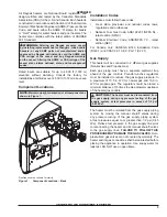
Attach Manometers to Measure Pressures
1. Turn off main gas valves.
2. Attach 24" scale manometer to the first main gas
shutoff valve pressure tapping.
3. Attach (1) 12" scale manometer to the outlet side of
the second main gas shutoff valve pressure tapping.
4. Attach (1) 12" scale manometer near the fan-proving
switch. Pull black cap from air pressure switch tee
and connect the manometer.
NOTE
: Retain caps for
reinstallation later.
NOTE:
The fan(s) pressure is already factory-set to
1.4 in. ± .1 in. WC (up to 4500 ft [11372 m] altitude). If
adjustment(s) is required, consult the appropriate Hi
Delta manual.
Check Gas Supply Pressure
1. Slowly turn on main gas shutoff valve.
2. Read the gas supply pressure from the manometer;
minimum supply pressure for natural gas is 5.6 in.
WC, recommended supply is 7.0 in. WC, minimum
supply pressure for propane gas is 11.0 in. WC
(dynamic readings, all stages firing).
3. If the pressure is > 14.0 in. WC, turn off the valve.
4. Check if the service regulator is installed and/or
adjust the service regulator.
A
WARNING:
This FlexGas heater is intended for
operation on Natural Gas as the primary fuel. DO NOT
use this heater with Propane Gas as the primary fuel.
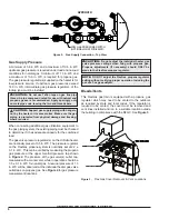
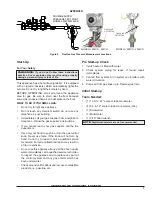
FlexGas System Start-up
1. Turn off unit. Ensure that the switch on the FlexGas
control is in the position marked “NAT”. See
Figure
5
for FlexGas control operation. Ensure the manual
valve on the natural gas supply is open and the
manual valve on the propane supply is closed.
2. Turn on the unit, wait 15 seconds, and the igniter
should glow. Look into sight glass located at each
end of the heater to check igniter operation. Gas
valves should open in 45-60 seconds.
3. If burner does not light on first trial. It will retry, up to
three times.
4. Main burner ignition: Check manifold gas pressure at
gas valve outlet pressure tap. This should read 3.5 ±
0.1 in. WC for natural gas. If the natural gas manifold
pressure is not within 3.5 ± 0.1 in. WC, follow the
instructions in the Hi Delta manual for adjusting
manifold pressure. If a flue gas analyzer is used,
the CO2 on natural gas should be 7.5-8.5% and CO
should be less than 150 ppm.
NOTE:
Do not adjust Hi Delta valve(s) or manifold
settings when operating on propane. These should only
be adjusted while firing natural gas.
5. When acceptable operation on Natural Gas is
confirmed, turn the gas selector key on the FlexGas
control to “OFF”.
6. Close the manual valve on the natural gas supply
then open the manual valve on the propane supply.
When the heater shuts off, turn the FlexGas control
key counter-clockwise to the “PRO” position.
7. Wait 15-seconds, and the igniter should glow. Look
into sight glass located at each end of the heater to
check igniter operation. Gas valves should open in
45-60 seconds.
8. If burner does not light on first trial. It will retry, up to
three times.
9. Main burner ignition: Check upper manifold gas
pressure.
10. If the pressure readings differ by more than ± 0.1
in. WC, remove screw cover from the gas pressure
regulator on the FlexGas fuel train and adjust until
upper manifold pressure is nominally 2.2 ± 0.1 in.
WC (manifold pressure 1.3 ± 0.1 in. WC). If a flue gas
analyzer is used, the CO2 on propane should be 9.0-
10.0% and CO should be less than 150 ppm.
APPROVED
UNCONTROLLED DOCUMENT IF PRINTED


