

5
All Raypak heaters are National Board registered, and
design-certified and tested by the Canadian Standards
Association (CSA) for the U.S. and Canada. Each heater is
constructed in accordance with Section IV of the American
Society of Mechanical Engineers (ASME) Pressure Vessel
Code, and bears either the ASME “H” stamp for boilers
or “HLW” stamp for water heaters and pool heaters. The
heater also complies with the latest edition of ASHRAE
90.1 Standard.
A
WARNING:
Altering any Raypak pressure vessel
by installing replacement heat exchangers, tube bundle
headers, or any ASME parts not manufactured and/or
approved by Raypak will instantly void the ASME and
CSA ratings of the vessel and any Raypak warranty
on the vessel. Altering the ASME or CSA ratings of the
vessel also violates national, state, and local approval
codes.
Rated inputs are suitable for up to 4,500 ft (1372 m)
elevation without de-rating. Consult the factory for
installations at altitudes over 4,500 ft (1372 m) above sea
level.
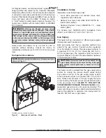
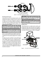
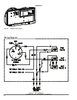
Component Locations
NOTE:
Maintain upright orientation of all components as
shown in Figure 1.
FlexGas cover not shown for clarity
Figure 1. Component Locations – Back
Installation Codes
Installations must follow these codes:
• Local, state, provincial, and national codes, laws,
regulations and ordinances
• National Fuel Gas Code, ANSI Z223.1/NFPA 54 –
latest edition (NFGC)
• National Electrical Code, ANSI/NFPA 70 - latest
edition (NEC)
For Canada only: CAN/CGA B149 Installation Code
(B149.1) and CSA C22.1 C.E.C. Part 1 (C22.1)
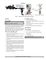
Gas Supply
This heater will be connected to 2 different gas supplies
(Natural Gas and Propane Gas).
Each gas piping must have a separate sediment trap
ahead of the gas controls. Pounds-to-inches regulators
must be installed to reduce the gas supply pressure to
a maximum of 10.5 in. WC for natural gas and 13.0 in.
WC for propane gas. The regulator should be placed a
minimum distance of 10 times the pipe diameter upstream
of the heater gas controls.
A
CAUTION:
The heater must be disconnected from
the gas supply during any pressure testing of the gas
supply system at test pressures in excess of 1/2 psi
(3.45 kPa).
The heater must be isolated from the gas supply piping
system by closing the manual shutoff valves during
any pressure testing of the gas supply piping system
at test pressures equal to or greater than 1/2 psi (3.45
kPa). Relieve test pressure in the gas supply line prior
to reconnecting the heater and its manual shutoff valves
to the gas supply lines.
FAILURE TO FOLLOW THIS
PROCEDURE MAY DAMAGE THE GAS VALVES
. Over-
pressurized gas valves are not covered by warranty. The
heater and its gas connections shall be leak-tested before
placing the appliance in operation. Use soapy water for
leak test. DO NOT use an open flame.
APPROVED
UNCONTROLLED DOCUMENT IF PRINTED


