Raynor COH Скачать руководство пользователя страница 12

5973132-12

INSPECTION AND ADJUSTMENTS

WARNING: Repairs and adjustments to the

door or operator should only be made

by a qualified door installer.

1.

2.

3.

4.

Inspect and tighten (if necessary) all bolts and nuts.

Periodically check that all labels shown on page 18

are installed. If labels are missing, contact your nearest
Raynor dealer.

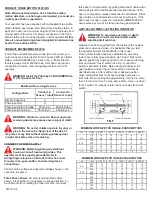
Adjust clutch as shown in Fig. 6, if necessary.

Adjustment may be required after a short break-in
period.

  If necessary, adjust limit nuts as described in Fig. 5.

5.

6.

7.

CAUTION: Do not reset overload until problem

             is identified. Damage to door and operator or

            personal injury could result if cause of tripping
             is not corrected.

8. Manual Reset Overload:

Single Phase:

Three Phase:

Check manual operation of door. Refer to

installation instructions 800, page 5972558-1
for guidelines.

Test all reversing devices once a month for proper

operation.

Test all accessories that may have been supplied with

the operator to ensure they are working properly.

The overload is properly

sized, at the factory, for normal door operation. If over-
load trips, manually check mechanical operation of door
and operator to be certain both work freely.

When overload trips, it cuts power to the

entire unit. To reset, press reset button on outside of
control box.

When overload trips, it cuts power to the

24 volt control circuit only. To reset, open control box
cover and press red reset button.

PERIODIC INSPECTION AND MAINTENANCE

Your Raynor electric door operator was designed to give dependable service with a minimum amount of maintenance.
After proper installation and adjustment, by a qualified installer, little is required in the way of maintenance except for
periodic inspection and lubrication as follows:

All Raynor operators are supplied with continuous rated
motors and under normal conditions require no oiling.

Lubricate rails with paraffin or graphite. Do not use oil or
grease on trolley drive chain or rails as it could drip onto

door.

     AMBIENT

TEMPERATURE

MOBIL OIL

HUMBLE

IMPERIAL OIL

AND GREASE

-20 F to 10 F

Vactra Oil No. 2 Spartan EP-2 Molub-Alloy 804

10 to 40 F

Vactra Oil No. 4 Spartan EP-2 Molub-Alloy 80

40 to 75 F

Mobilgear 632 Spartan EP-4 Molub-Alloy 90

75 to 105 F

600 W Super

Cylinder Oil

Spartan EP-6 Molub-Alloy 140

LUBRICATION

The gearbox is supplied from the factory with oil for a temperature range of -20  to 90 F. For special conditions or if oil
needs to be added, follow the recommendations below:

Note:

  Some gear lubricants contain corrosive extreme pressure additives. Do not use lubricants that are compounded

with sulphur and/or chlorine. These may be corrosive to bronze worm gears.

Содержание COH

Страница 1: ...Chain Hoist Special Application Jackshaft IMPORTANT PLEASE READ THESE INSTRUCTIONS BEFORE STARTING INSTALLATION IT IS IMPORTANT THAT THIS OPERATOR BE INSTALLED CORRECTLY IN ORDER TO ACHIEVE SAFE AND...

Страница 2: ...y of the consumer and must be performed by an authorized Raynor Dealer This warranty extends only to the original purchaser This warranty is not transferable Raynor shall not be liable for any consequ...

Страница 3: ...s 9 Do not place hands in area of pulleys V belt sprockets chain or rotating shafts 10 Install warning placard on wall next to push button 11 Attach instruction booklet to wall near push button 12 Do...

Страница 4: ...ining the operator itself one drive and one driven sprocket one length of chain one control station and one package of small hardware Unpack carton being certain that all loose parts are removed befor...

Страница 5: ...est results Place small drive sprocket on proper side of operator shaft as shown in Fig 3 Remove base mounting plate from operator see Fig 3 and use as a template for drilling holes in wall then re in...

Страница 6: ...ator and set limit switches in this mode Once correct rotation has been established manually lower door to fully closed position Set close limit nut at desired position by depressing limit nut keeper...

Страница 7: ...ten the belleville springs See Fig 6 If additional tension is required add extra belleville springs to clutch assembly WARNING Do NOT over tension clutch Note The clutch is set loose at the factory an...

Страница 8: ...Power Connection Terminal Block 1 Terminal Block 2 High Voltage Wire Harness Connection LIGHT CCM NO1 SER C1NC1 NO2 C2NC2 ON OFF OPEN CLOSE ON OFF 24VDC 24VDC 24VAC 24VAC Terminal Block 3 24V DC Power...

Страница 9: ...sing RD or RC wiring photo eye s or edge must be selected even though they are not required Note The photo eye or an electric edge must be monitored 5 SENSOR 2 TYPE will display there are three option...

Страница 10: ...warning light is required select OFF If a warning light is required select ON Press the stop button to continue 16 If a warning light is ON WARNING TIME will display The time is set in 1 second inter...

Страница 11: ...r death 8 SAVE THESE INSTRUCTIONS OPERATING INSTRUCTIONS Operating the 3 Button Control Station 1 Press OPEN button The door should move in the open direction 2 Press STOP button The door should stop...

Страница 12: ...eset press reset button on outside of control box When overload trips it cuts power to the 24 volt control circuit only To reset open control box cover and press red reset button PERIODIC INSPECTION A...

Страница 13: ...ng Off Stop button pressed or NOT connected On Open button sending signal pressed Off Open button is not sending signal 2 Open D12 6 I Lock D24 7 I Lock D23 On Chain hoist interlock circuit is open ch...

Страница 14: ...ton to pause this countdown Sensor 1 activated This message will display anytime the board is not receiving a signal from the sensor 1 when close button is pressed Whether it is not connected activate...

Страница 15: ...minate stress on rollers and cables 1 Sunlight is blocking the receiving photo eye 2 Faulty photo eyes 1 Connect Operator to power source 2 Check voltage at L1 L2 for single phase and at L1 L2 L3 for...

Страница 16: ...oard Verify power consumption of the device s before installing You may have to power the device from an external power source using only the contacts of the device to activate the operator 3 The comm...

Страница 17: ...use the dry contacts of that relay to activate the device If more than 3 amps of power is being consumed through the auxiliary board then damage to the board may occur 2 There is a 14 pin connector o...

Страница 18: ...nger anger La Label el Door oor Safet Safety y La Label el Spring Spring Warning ning Tag ag Pu Push Button h Button Placa Placard Locate n Locate near Push Button Push Button Door oor Safet Safety y...

Отзывы: