background image

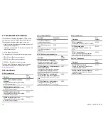
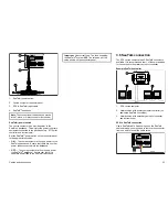
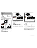
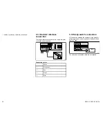
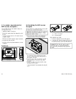
3.5 Fuses and circuit protection

Power supply circuit protection

The power supply must be connected using an
appropriately rated and fused switch or thermal breaker.
The drive type determines the rating of the breaker or
fuse required.

Drive unit

Supply
voltage

Fuse

Thermal
over-
current
circuit
breaker

0.5 l
hydraulic
pump

12 V

15 A

10 A

Type 1

(Rotary,
Linear or
Hydraulic)

12 or 24 V

25 A

20 A

12 V

40 A

30 A

Type 2

(Rotary,
Linear or
Hydraulic)

24 V

30 A

30 A

Type 3

(

Hydraulic
linear)

12 V or 24 V

40 A

30 A

I/O

12 V

15 A

10 A

CR pump
(Solenoid)

12 or 24 V

10 A

10 A

Internal fuses

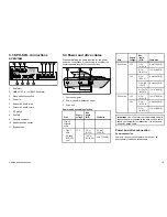
The course computer uses standard automotive blade
fuses. Spare fuses are located on underside of the
removable cover.

Rayma rine  

GROUND

P OWER

P OWER

P

O

W

E

R

12V

OFF

ON

24V

FLUXGATE

RUDDER

CLUTCH

FAULT

S LEEP

FAULT

MOTOR

A

B

D11937-1

2

1

3

1.

SeaTalk

ng

fuse. (Fuse power supply from course

computer to SeaTalk

ng

backbone.

2.

SeaTalk fuse. (Fuse power supply from course
computer to connected SeaTalk devices).

3.

Power fuse. (Fuse total power consumed by
system, including the drive unit.)

SeaTalk

ng

SeaTalk

Power

SPX-10

2 A

2 A

15 A

SPX-30

3 A

3 A

40 A

SOX-
SOL

3 A

3 A

15 A

3.6 Grounding

These grounding requirements are applicable for
Raymarine equipment with a dedicated ground terminal.

• The ground terminal must be connected to a common

ground point.

• It is recommended that the common ground point is a

bonded ground, i.e. with the ground point connected
to battery negative, and situated as close as possible
to the battery negative terminal. If a bonded ground
system is not possible, a non-bonded RF ground may
be used.

Bonded ground system (preferred)

D

1

1

9

4

0

-1

2

4

3

1

RF ground system (alternative)

D

1

1

9

4

1

-1

2

4

3

1

1.

Ground terminal. (This may also be labelled as
Ground, or Screen.)

2.

Ground braid.

3.

Bonded (preferred) or non-bonded RF ground.

4.

Power supply or battery.

Cables and connections

21

Содержание SPX 10

Страница 1: ...Installation instructions ENGLISH Date 07 2012 Document number 87072 4 EN 2012 Raymarine UK Limited S P X 1 0 S P X 3 0 S P X S OL SPX10 SPX30 SPX SOL ...

Страница 2: ......

Страница 3: ...ts patents pending or design patents pending Fair Use Statement You may print no more than three copies of this manual for your own use You may not make any further copies or distribute or use the manual in any other way including without limitation exploiting the manual commercially or giving or selling copies to third parties Software updates Check the website www raymarine com for the latest so...

Страница 4: ......

Страница 5: ...rive cables 19 3 5 Fuses and circuit protection 21 3 6 Grounding 21 3 7 SPX to SeaTalkng connection 22 3 8 SeaTalk connection 23 3 9 NMEA 0183 connection 25 3 10 Compass connection 25 3 11 Rudder reference connection 26 3 12 Sleep switch connection 26 Chapter 4 Installation 27 4 1 Location requirements for SPX course computers 28 4 2 Installing the SPX course computer 28 4 3 Initial checks for the...

Страница 6: ...6 SPX10 SPX30 SPX SOL ...

Страница 7: ...NOT approved for use in hazardous flammable atmospheres Do NOT install in a hazardous flammable atmosphere such as in an engine room or near fuel tanks Warning Switch off power supply Ensure the vessel s power supply is switched OFF before starting to install this product Do NOT connect or disconnect equipment with the power switched on unless instructed in this document Warning Product grounding ...

Страница 8: ...levant product page at www raymarine com Product disposal Dispose of this product in accordance with the WEEE Directive The Waste Electrical and Electronic Equipment WEEE Directive requires the recycling of waste electrical and electronic equipment Whilst the WEEE Directive does not apply to some Raymarine products we support its policy and ask you to be aware of how to dispose of this product War...

Страница 9: ...on on page 10 2 2 Installation checklist on page 11 2 3 Inboard autopilot system on page 11 2 4 SeaTalkng autopilot system on page 12 2 5 SeaTalk autopilot system on page 14 2 6 Parts supplied on page 15 2 7 Required additional components on page 15 Planning the installation 9 ...

Страница 10: ...tion Part number p70 p70R Installation and commissioning instructions 87132 p70 p70R Quick reference guide 86142 p70 p70R User reference handbook 81331 ST70 Pilot Controller handbooks Description Part number ST70 Pilot Controller Installation Mounting and connection of the ST70 Pilot controller as part of the SmartPilot system 87071 ST70 Pilot Controller Commissioning for SPX autopilot systems Com...

Страница 11: ...h helm position 2 Course computer This is the central intelligence hub of the autopilot system linking the control head to the drive unit 3 Drive unit The drive unit interfaces with your boat s steering system 4 Fluxgate compass The fluxgate compass provides the autopilot with a magnetic heading required for maintaining a course 5 Rudder reference Required for some systems only This provides feedb...

Страница 12: ... ENTER CANCEL MENU SeaT alkng SeaT alkng SeaT alkng SeaT alkng 12 24 V 1 2 ENTER CANCEL MENU ENTER CANCEL MENU ENTER CANCEL MENU 3 4 5 6 SMARTPIL OT 1 Multifunction display with GPS GPS may be internal or external 2 Autopilot controller and instruments e g helm 1 3 Autopilot controller and instruments e g helm 2 12 SPX10 SPX30 SPX SOL ...

Страница 13: ...draw can be powered from the network although high current equipment will need to have a separate power connection SeaTalkng is a proprietary extension to NMEA 2000 and the proven CAN bus technology Compatible NMEA 2000 and SeaTalk SeaTalk2 devices can also be connected using the appropriate interfaces or adaptor cables as required NMEA 2000 NMEA 2000 offers significant improvements over NMEA 0183...

Страница 14: ...terface Standard was developed by the National Marine Electronics Association of America It is an international standard to enable equipment from many different manufacturers to be connected together and share information The NMEA 0183 standard carries similar information to SeaTalk However it has the important difference that one cable will only carry information in one direction For this reason ...

Страница 15: ...X core pack Compatible autopilot controller Drive unit appropriate for your boat and autopilot course computer Power and drive cables Autopilot controllers There are a number of autopilot controllers available for connection to your system The autopilot controller may be connected using either SeaTalkng or SeaTalk depending upon the course computer and any existing marine electronics connected S10...

Страница 16: ...SPX 10 Mechanical linear drives used in sailing vessels the mechanical linear drive moves the rudder directly by pushing the tiller arm or a rudder quadrant Type 2 SPX 30 Type 1 SPX 10 Mechanical rotary drives designed for power and sailboat systems that can be driven from the helm position through a chain and sprocket e g cable and rod Type 2 SPX 30 Universal stern drive SPX 10 CR Pump Solenoid S...

Страница 17: ...on page 19 3 4 Power and drive cables on page 19 3 5 Fuses and circuit protection on page 21 3 6 Grounding on page 21 3 7 SPX to SeaTalkng connection on page 22 3 8 SeaTalk connection on page 23 3 9 NMEA 0183 connection on page 25 3 10 Compass connection on page 25 3 11 Rudder reference connection on page 26 3 12 Sleep switch connection on page 26 Cables and connections 17 ...

Страница 18: ...uipment and cables high current carrying ac and dc power lines antennae Strain relief Ensure adequate strain relief is provided Protect connectors from strain and ensure they will not pull out under extreme sea conditions Circuit isolation Appropriate circuit isolation is required for installations using both AC and DC current Always use isolating transformers or a separate power inverter to run P...

Страница 19: ...nel 3 Drive unit Power and drive cable selection Drive Supply voltage Max length A B Cable size Type 0 5 hydraulic pump 0 7 m 0 23 ft 2 5 mm2 14 AWG Type 1 drive CR pump SPX SOL only 12 V 7 10 m 23 32 8 ft 4 mm2 12 AWG Drive Supply voltage Max length A B Cable size 0 5 m 0 16 4 ft 6 mm2 10 AWG 12 V 5 7 m 16 4 23 ft 10 mm2 8 AWG 0 3 m 0 9 8 ft 4 mm2 12 AWG 3 5 m 9 8 16 4 ft 6 mm2 10 AWG Type 2 driv...

Страница 20: ...e has a separate clutch connection to the course computer you must ensure that the clutch voltage switch is set correctly Note The clutch voltage may be different from that of the drive itself for example the range of both 12 and 24 V Raymarine drives all have a 12 V clutch Solenoid drive connection GROUND POWER SOLENOID SOLENOID A B 12 V 24 V D10456 2 1 2 3 4 5 1 Electronic steering jog lever if ...

Страница 21: ...g fuse Fuse power supply from course computer to SeaTalkng backbone 2 SeaTalk fuse Fuse power supply from course computer to connected SeaTalk devices 3 Power fuse Fuse total power consumed by system including the drive unit SeaTalkng SeaTalk Power SPX 10 2 A 2 A 15 A SPX 30 3 A 3 A 40 A SOX SOL 3 A 3 A 15 A 3 6 Grounding These grounding requirements are applicable for Raymarine equipment with a d...

Страница 22: ...ARTPIL OT D10437 2 4 1 3 2 SeaT alkng 1 Helm position with SeaTalkng autopilot controller and instrument 2 SeaTalkng backbone 3 Helm position with SeaTalkng autopilot controller and instrument 4 SPX course computer You can connect an autopilot controller at each helm position Note Only autopilot controllers compatible with SeaTalkng can be connected to the backbone SeaTalk to SeaTalkng Converter T...

Страница 23: ...ckbone OFF The course computer will not supply power the SeaTalkng backbone Ensure that there is a separate power feed to the SeaTalkng backbone Important Use correct fuse The fuse supplying the SeaTalkng system MUST be rated as per the value shown on the connector panel 3 8 SeaTalk connection The SPX course computer has 2 SeaTalk connectors available It is recommended that 1 of these is reserved ...

Страница 24: ...onnect power red and screen grey at both sets of terminals Connect data yellow at one end only Cut back and insulate unconnected data wire The autopilot controller should be the first device on the ring working from the course computer data connection SeaTalk connected with its own power supply SeaT alk SMARTPIL OT D10440 2 1 2 1 Course computer power supply via breaker fuse 2 SeaTalk power supply...

Страница 25: ... connected using SeaTalkng Example FastHeading connection D11220 3 SMARTPIL OT NM EA0183 SeaT alk 1 2 4 3 5 Note The connection can be made into any NMEA 0183 input at the display 1 Multifunction display 2 Autopilot course computer 3 NMEA 0183 FastHeading and other relevant data 4 Autopilot controller 5 Fluxgate compass 3 10 Compass connection The fluxgate compass connects to the course computer c...

Страница 26: ...UXGATE RUDDER CLUTCH SLEEP POWER D10462 2 3 4 1 2 Connection colors Color 1 Grey screen 2 Red 3 Green 4 Blue 3 12 Sleep switch connection A Sleep switch disables the operation of the autopilot while retaining any power supplied to the SeaTalk and SeaTalkng bus POWER OFF ON FAULT SLEEP FAULT NMEA D10463 2 The switch and associated cable are not supplied 26 SPX10 SPX30 SPX SOL ...

Страница 27: ...tallation Chapter contents 4 1 Location requirements for SPX course computers on page 28 4 2 Installing the SPX course computer on page 28 4 3 Initial checks for the autopilot installation on page 29 Installation 27 ...

Страница 28: ...on hard standing or tied up alongside a pontoon or berth 1 Mount the course computer in an appropriate location and secure with the screws supplied D10448 2 You should also mount the fluxgate compass autopilot controller and rudder reference unit if appropriate at this time 2 Route the power data compass and any other cables required for connection to the course computer 3 Make all necessary conne...

Страница 29: ...upply 2 Check that the autopilot controller powers up If the display is blank press and hold the Power key for 1 second 3 Check the display for error messages that could indicate a problem with the installation For assistance with diagnosing faults Refer to the troubleshooting information supplied with the product or contact Raymarine customer support Note The autopilots built in gyro requires a f...

Страница 30: ...30 SPX10 SPX30 SPX SOL ...

Страница 31: ...Chapter 5 Maintenance and support Chapter contents 5 1 Service and maintenance on page 32 5 2 Cleaning on page 32 5 3 Raymarine customer support on page 32 Maintenance and support 31 ...

Страница 32: ...e to resolve a problem please use any of these facilities to obtain additional help Web support Please visit the customer support area of our website at www raymarine com This contains Frequently Asked Questions servicing information e mail access to the Raymarine Technical Support Department and details of worldwide Raymarine agents Telephone and email support In the USA Tel 1 603 324 7900 Toll F...

Страница 33: ... 11 2 in Height 212 mm 2 5 in Depth 65 mm 8 3 in Weight 1 1 kg 2 42 lbs SPX 10 2 2 kg 4 85 lbs SPX 30 Data Connections NMEA 0183 I O 4800 baud SeaTalkng SeaTalk Other connections Fluxgate compass Rudder position sensor Sleep switch Power drive motor drive clutch SOL bypass valve Fast heading output NMEA 0183 5 Hz SeaTalkng 10 Hz NMEA 2000 10 Hz Raymarine drive compatibility X 10 X 30 X SOLENOID SP...

Страница 34: ... and speed over ground SOG VWR Apparent wind angle AWA and apparent wind speed AWS XTE Cross track error ZDA Time and date Transmit NMEA 0183 out HDG Heading deviation and variation HDT True heading requires true heading data to be available RSA Rudder angle requires rudder reference unit Appendix C SeaTalkng cables and accessories SeaTalkng cables and accessories for use with compatible products ...

Страница 35: ...eaTalk2 5 pin to SeaTalkng adaptor cable 0 4 m 1 3 ft A06048 DeviceNet adaptor cable Female A06045 Allows the connection of NMEA 2000 devices to a SeaTalkng system DeviceNet adaptor cable Male A06046 Allows the connection of NMEA 2000 devices to a SeaTalkng system DeviceNet adaptor cable Female to bare ends E05026 Allows the connection of NMEA 2000 devices to a SeaTalkng system DeviceNet adaptor c...

Страница 36: ...36 SPX10 SPX30 SPX SOL ...

Страница 37: ......

Страница 38: ...www raymarine com ...

Отзывы: