A B
2
1
D
11946-2
P OWER
P
O
W
E
R
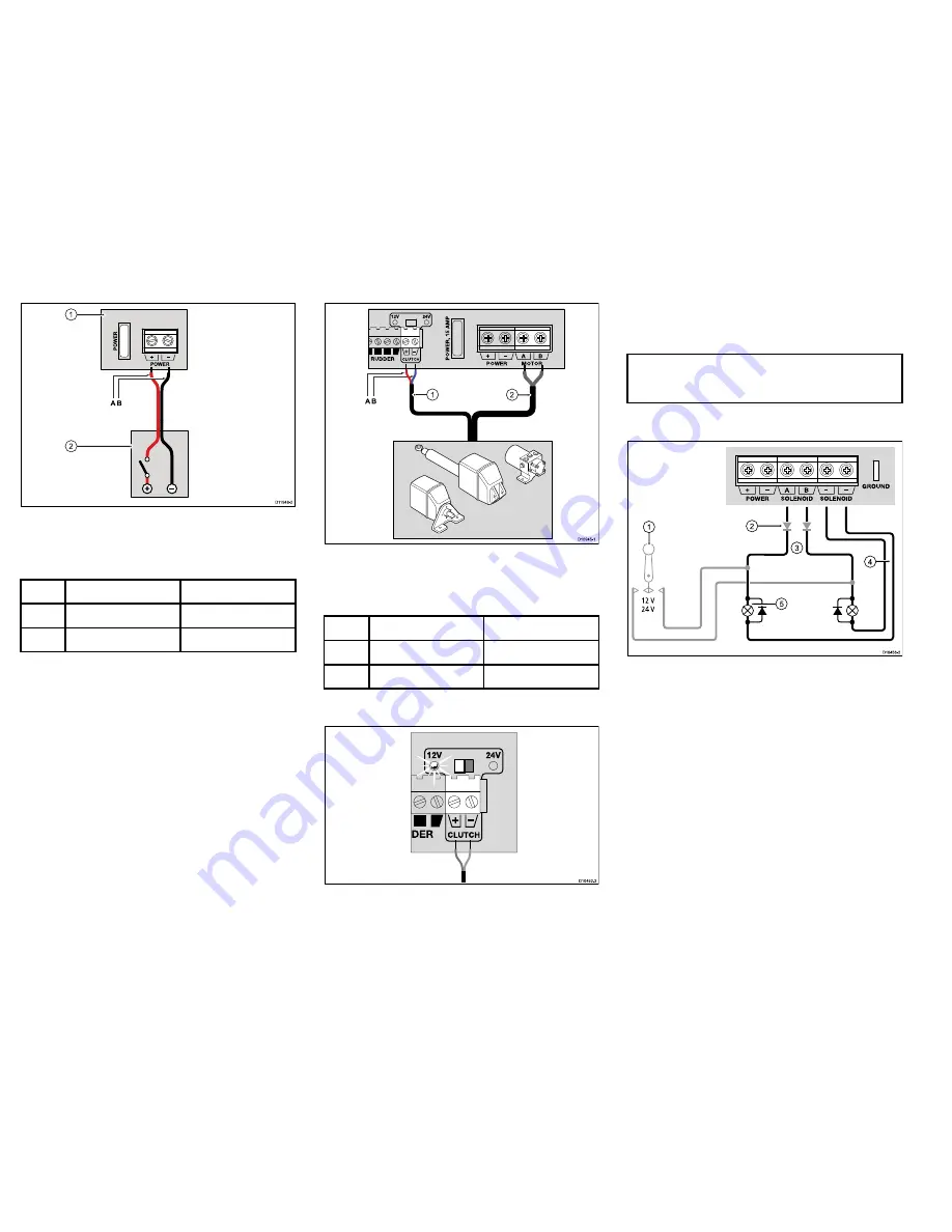
1.
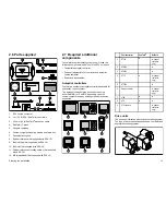
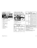
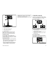
Course computer connection panel
2.
Power distribution panel
Power connection colors
Color
Description
A
Red
Power in +ve (12 / 24 V)
B
Black
Power in -ve (0 V)
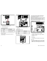
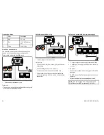
Drive connection
The drive connects to the connection panel of the
course computer.
D10945-1
A
B
MADE IN HUNGARY
GROUND
P
O
W
E
R
,
1
5
A
M
P
12V
24V
FLUXGATE
RUDDER
CLUTCH
S LEEP
P OWER
B
MOTOR
A
2
1
1.
Clutch (not all drives have this connection)
2.
Motor/drive
Clutch connection colors
Color
Description
A
Red
ve
B
Blue
Clutch -ve
Clutch voltage switch
D10452-2
If the drive has a separate clutch connection to the
course computer, you must ensure that the clutch
voltage switch is set correctly.
Note:
The clutch voltage may be different from that
of the drive itself, for example the range of both 12
and 24 V Raymarine drives all have a 12 V clutch.
Solenoid drive connection
G
ROUND
P OWER
S OLENOID
S OLENOID
A
B
12 V
24 V
D10456-2
1
2
3
4
5
1.
Electronic steering / jog lever (if required)
2.
Back-feed protection diodes (if using a electronic
steering or jog lever)
3.
Drive out.
4.
Drive return
5.
Solenoid valves (with diodes across spool valves)
Care points:
• If an electronic steering or jog lever is used, fit diodes
(suggested type: 1N4004) in line with the solenoid
outputs to prevent back-feeding the course computer.
20
SPX10, SPX30, SPX-SOL
Содержание SPX 10
Страница 2: ......
Страница 4: ......
Страница 6: ...6 SPX10 SPX30 SPX SOL ...
Страница 30: ...30 SPX10 SPX30 SPX SOL ...
Страница 36: ...36 SPX10 SPX30 SPX SOL ...
Страница 37: ......
Страница 38: ...www raymarine com ...


