
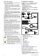


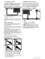


4.20 Thermal camera connection
Thermal cameras can be connected directly to the
display’s network connection or can be connected to
the
SeaTalk
hs
network, via a
Raymarine
®
network
switch.
2 connections are required:
•
Network connection
— required to control the
thermal camera via a compatible
Raymarine
®
MFD
or optional Joystick Control Unit (JCU).
•
Video connection
— transmits the composite
video signal to a compatible
Raymarine
®
MFD
.
Note:
The Thermal camera can only be connected
to
MFD
s with a Video input connection.
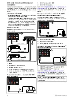
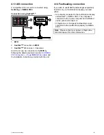
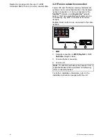
T200 Series connection
D12839-2
3
2
1
4
5
6
7
1.
MFD
2.
Thermal camera
3.
Power over Ethernet (PoE) Injector
4.
RayNet
to RJ45
SeaTalk
hs
adaptor cable
5.
Network connection to
MFD
(
RayNet
)
6.
Video connection to
MFD
(composite video)
7.
Video cable
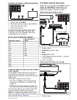
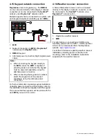
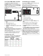
T300 / T400 Series connection.
SeaTalk
hs
/ RayNet
SeaTalk
hs
/ RayNet
SeaTalk
hs
/ RayNet
D12260-2
6
7
4
9
3
2
1
5
8
1
0
1.
MFD
2.
Video connection to
MFD
(composite video)
3.
Network connection to
MFD
(
RayNet
cable)
4.
Raymarine
®
network switch
5.
Video cable
6.
RayNet
to RJ45
SeaTalk
hs
adaptor cables
7.
PoE (Power over Ethernet) injector (only
required if using the optional JCU)
8.
Thermal camera
9.
Joystick Control Unit (JCU), optional
10. Ethernet coupler (R32142)
Important:
• You can only view the thermal camera image on
the multifunction display to which the camera is
physically connected. If you want to view the
thermal camera image on more than 1 display
you must obtain a suitable third-party video
distribution unit.
• You can control the thermal camera using any
multifunctional display connected to the same
network. The Joystick Control Unit (JCU) is
optional, but can be used in conjunction with
multifunctional displays to control the thermal
camera if required.
• “Dual payload” thermal cameras include 2
independent lenses; 1 for thermal (infrared) and
1 for visible light. If you only have 1 display you
should only connect the video cable labelled
“VIS / IR” (visible light / infrared) to the display. If
you have 2 or more displays you should connect
1 cable to each display.
For further information regarding thermal camera
installation (including power connection and
mounting), refer to the installation instructions
supplied with the camera.
Thermal camera cables
Cabling requirements for thermal cameras.
Camera to network switch
A network patch cable is required to connect the
camera to the network switch. The connection is
made between the camera cable tail and the network
switch via the coupler (supplied with the camera).
Network patch cables are available in a variety of
lengths.
Joystick Control Unit (JCU)
An Ethernet (with power) cable is used to connect the
JCU. The JCU is supplied with a 1.5 m (5 ft) Ethernet
cable for this connection. If you require a different
length contact your dealer for suitable cables.
Power over Ethernet (PoE) injector to network
switch
A network patch cable is required for connecting the
PoE injector to the network switch. Network patch
cables are available in a variety of lengths.
Video cables
Video cables are not supplied with the product.
Please contact your dealer for suitable cables and
adaptors.
Cables and connections
49
Содержание eS Series
Страница 2: ......
Страница 4: ......
Страница 30: ...30 eS Series installation instructions...
Страница 56: ...56 eS Series installation instructions...
Страница 92: ...92 eS Series installation instructions...
Страница 114: ...114 eS Series installation instructions...
Страница 124: ...124 eS Series installation instructions...
Страница 128: ...128 eS Series installation instructions...
Страница 138: ...138 eS Series installation instructions...
Страница 146: ...146 eS Series installation instructions...
Страница 147: ......
Страница 148: ...www raymarine com...