Raymarine eS Series Скачать руководство пользователя страница 48

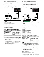
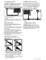
4.19 IP Camera connection

Raymarine

®

IP cameras can be connected

directly to the display’s network connection or can
be connected to the

SeaTalk

hs

network, via a

Raymarine

®

network switch.

The network connection transmits the video signal to
a compatible

Raymarine

®

MFD

.

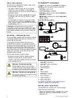
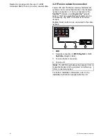
IP camera direct connection

D12592-5

3

4

2

1

1.

MFD

2.

CAM200IP

3.

RayNet

to RJ45

SeaTalk

hs

adaptor cable

4.

Ethernet coupler (R32142)

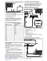
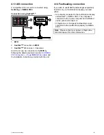
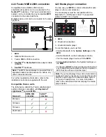
IP camera network connection

D12593-5  

4

3

2

5

5

5

5

3

3

3

4

4

4

1

1.

MFD

2.

Raymarine

®

network switch

3.

RayNet

to RJ45

SeaTalk

hs

adaptor cable

4.

Ethernet coupler (R32142)

5.

CAM200IP

Important:

If your IP camera(s) are not detected

by your multifunction display, try power cycling
the IP camera(s) whilst leaving your multifunction
display powered up.

For further information regarding camera installation
(including power connection and mounting), refer to
the installation instructions supplied with the camera.

IP camera guidance

Raymarine

®

MFD

s are capable of displaying IP

camera feeds. Whilst third-party IP cameras may
work,

Raymarine

®

highly recommends only using

Raymarine

®

IP cameras such as the

CAM200IP

.

As guidance any third-party IP camera must conform
to the following:

• The camera must support H.264 compression and

RTSP (Real time Streaming Protocol).

• The camera must be ONVIF compliant

• The camera must be capable of and be setup to

allow unauthenticated anonymous access

• The camera must be capable of and be setup to

assign an IP address automatically via DHCP

• The camera resolution must be set to no higher

than 720p

The camera settings must be checked and if
necessary adjusted using a PC and the software
supplied with the camera, prior to adding the camera
to the

SeaTalk

hs

network.

Important: Raymarine

®

does not guarantee

compatibility with third-party IP cameras.

48

eS Series installation instructions

Содержание eS Series

Страница 1: ...eS Series Installation instructions English Date 05 2015 Document number 87250 1 EN 2015 Raymarine UK Limited...

Страница 2: ......

Страница 3: ...patents design patents patents pending or design patents pending Fair Use Statement You may print no more than three copies of this manual for your own use You may not make any further copies or dist...

Страница 4: ......

Страница 5: ...ule and transducer connection 40 4 10 Radar network connection 41 4 11 GA150 connection 44 4 12 GNSS GPS connection 44 4 13 AIS connection 45 4 14 Fastheading connection 45 4 15 Keypad network connect...

Страница 6: ...s and storage eS7x displays 120 10 10 Data connections and storage eS9x and eS12x displays 120 10 11 Environmental specification 121 10 12 Internal GNSS GPS GLONASS receiver specification 121 10 13 In...

Страница 7: ...rning FCC Warning Part 15 21 Changes or modifications to this equipment not expressly approved in writing by Raymarine Incorporated could violate compliance with FCC rules and void the user s authorit...

Страница 8: ...use a jet wash TFT Displays The colors of the display may seem to vary when viewed against a colored background or in colored light This is a perfectly normal effect that can be seen with all color T...

Страница 9: ...nada This device complies with Industry Canada License exempt RSS standard s Operation is subject to the following two conditions 1 This device may not cause interference and 2 This device must accept...

Страница 10: ...you register your product to receive full warranty benefits Your unit package includes a bar code label indicating the serial number of the unit You will need this serial number when registering your...

Страница 11: ...Chapter contents 2 1 Document information on page 12 2 2 Applicable products on page 12 2 3 Product documentation on page 13 2 4 Document illustrations on page 13 2 5 Product overview eS Series on pa...

Страница 12: ...rt of a wider system of connected marine electronics troubleshoot problems and obtain technical support if required This and other Raymarine product documents are available to download in PDF format f...

Страница 13: ...Raymarine product Visit http www raymarine co uk view id 5175 to order a printed manual delivered directly to your door For further information about the Print Shop please visit the Print Shop FAQ pag...

Страница 14: ...o operate the unit using the touchscreen and the physical buttons A HybridTouch display has physical buttons which can be used in addition to the touchscreen Touchscreen only multifunction displays wh...

Страница 15: ...page 22 3 4 Identifying your display variant on page 23 3 5 Networking constraints on page 23 3 6 System protocols on page 24 3 7 Data master on page 25 3 8 Parts supplied eS7x displays on page 26 3...

Страница 16: ...1 per MFD Raymarine RCU 3 Bluetooth 2 Mobile device Smartphone Tablet 1 per multifunction display For Raymarine wireless video streaming and remote control apps Apple iPhone 4 or later or iPad 2 or l...

Страница 17: ...ed or Tridata i60 Wind CH Wind i70 ST70 ST70 SeaTalk via optional SeaTalk to SeaTalkng converter i40 Wind Speed Depth or Bidata ST60 Wind Speed Depth Rudder or Compass ST40 Wind Speed Depth Rudder or...

Страница 18: ...g Man overboard alert 1 basestation All Raymarine Lifetag basestations SeaTalk via optional SeaTalk to SeaTalkng converter 12 Engine interface Raymarine 1 unit for each engine CAN bus ECI 100 SeaTalkn...

Страница 19: ...rnal sonar variant displays 15 DownVision transducers 1 Direct connection to internal CHIRP DownVisionTM variant displays CPT 100 Transom mount CPT 110 Thru hull plastic CPT 120 Thru hull bronze Direc...

Страница 20: ...4 Connections to multifunction display NMEA inputs 2 NMEA 0183 compatible chartplotters and multifunction displays NMEA 0183 19 Sonar Modules Fishfinder Raymarine Multiple CP100 DownVision CP200 SideV...

Страница 21: ...Multiple Fusion 700 series entertainment systems MS IP700 MS AV700 SeaTalkhs 24 PC laptop 1 Windows compatible PC or laptop running Raymarine Voyage Planner software SeaTalkhs Note Raymarine cannot gu...

Страница 22: ...ded If this exercise is NOT completed the system will automatically attempt to resolve data conflicts However this may result in the system choosing a source of data that you do not want to use If MDS...

Страница 23: ...d as the Data Master The Data Master display will receive data through NMEA 0183 and or SeaTalkng and bridge the data over SeaTalkhs to other networked displays Homescreen sharing When networked MFDs...

Страница 24: ...r system does not use all of the connection types or instrumentation described in this section SeaTalkhs SeaTalkhs is an ethernet based marine network This high speed protocol allows compatible equipm...

Страница 25: ...are used some examples of which are VTG carries Course and Speed Over Ground data GLL carries latitude and longitude DBT carries water depth MWV carries relative wind angle and wind speed data NMEA B...

Страница 26: ...s 4 3 9 Parts supplied eS9x and eS12x displays 1 3 5 6 9 10 11 12 7 8 4 2 x4 D13329 1 Item Description Quantity 1 Multifunction display 1 2 Sun cover 1 3 Panel seal gasket 1 4 Trunnion bracket and kno...

Страница 27: ...system component are provided later in this chapter Mounting surface Ensure product is adequately supported on a secure surface Do not mount units or cut holes in places which may damage the structur...

Страница 28: ...ecks D11537 2 1 2 3 1 2 3 1 This location provides optimal GPS performance above decks 2 In this location GPS performance may be less effective 3 This location is NOT recommended for GPS antenna Vesse...

Страница 29: ...throughout the installation Viewing angle considerations As display contrast color and night mode performance are all affected by the viewing angle Raymarine recommends you temporarily power up the di...

Страница 30: ...30 eS Series installation instructions...

Страница 31: ...onnection on page 41 4 11 GA150 connection on page 44 4 12 GNSS GPS connection on page 44 4 13 AIS connection on page 45 4 14 Fastheading connection on page 45 4 15 Keypad network connection on page 4...

Страница 32: ...moving or hot objects Secure cables in place using tie wraps or lacing twine Coil any extra cable and tie it out of the way Where a cable passes through an exposed bulkhead or deckhead use a suitable...

Страница 33: ...3 Video in Power Power NMEA Video eS75 eS77 eS78 eS97 eS98 eS127 eS128 Connector and cable protective caps Unused connectors and disconnected cables should be adequately protected against damage Impor...

Страница 34: ...ow apply to MFDs that have a combined power NMEA video cable Refer to the Connections Overview section to establish the power connection for your MFD D13283 2 2 1 4 5 7 3 8 6 9 1 MFD 2 Combined Power...

Страница 35: ...your product s power cable is supplied with a separate drain wire then it should be connected to the vessel s common ground point B Battery connection scenario B suitable for a vessel without a common...

Страница 36: ...hould be connected directly to the negative battery terminal The dc power system should be either Negative grounded with the negative battery terminal connected to the vessel s ground Floating with ne...

Страница 37: ...ng backbone and connect each NMEA 2000 device on a spur OR connect the display on a spur into an existing NMEA 2000 backbone Important You cannot have 2 backbones connected together Connecting NMEA 20...

Страница 38: ...4800 or 38400 baud rate Port 2 Input only 4800 or 38400 baud rate The baud rate for each input port must be specified in the System Settings menu Homescreen Set up System Settings NMEA Set up NMEA In...

Страница 39: ...NMEA Input Port Note For Port 1 both the input and output communicate at the same baud rate For example if you have one NMEA 0183 device connected to Port 1 INPUT and another NMEA 0183 device connecte...

Страница 40: ...RP DownVisionTM sonar module Transducer connection Internal 600 W MFD direct connection 2 D12256 2 1 3 1 600 W sonar variant MFD 2 600 W MFD transducer Refer to 12 2 Digital ClearPulse Transducers and...

Страница 41: ...This applies to systems which include Any number of MFD s with an internal sonar module plus a CP300 and or CP450C sonar module or No MFD s with an internal sonar module but more than one CP300 or CP...

Страница 42: ...digital cable extension is required D12254 1 1 4 2 3 1 Radar extension cable 2 Radar power and data digital cable 3 Raymarine network switch or crossover coupler if connecting Radar directly to displ...

Страница 43: ...cable A55079D Note The maximum length for the radar power and data digital cable including any extensions is 25 m 82 ft RayNet Radar power and data digital cables These cables contain the wires for a...

Страница 44: ...l result in signal degradation Connecting an external antenna Follow the steps below to connect the GA150 external antenna 1 3 2 4 D13074 1 1 Fully insert the antenna s cable connector into the GA150...

Страница 45: ...allation instructions provided with the unit 4 14 Fastheading connection If you wish to use MARPA radar target acquisition functions on your multifunction display you need either An autopilot connecte...

Страница 46: ...ernate power connection For further information regarding keypad installation including power connection and mounting refer to the installation instructions supplied with the keypad Once connected the...

Страница 47: ...not have a direct connection to the vessel s dc power supply For further assistance please contact Raymarine technical support 4 18 Video connection composite Analog cameras can be connected directly...

Страница 48: ...ing power connection and mounting refer to the installation instructions supplied with the camera IP camera guidance Raymarine MFDs are capable of displaying IP camera feeds Whilst third party IP came...

Страница 49: ...on unit You can control the thermal camera using any multifunctional display connected to the same network The Joystick Control Unit JCU is optional but can be used in conjunction with multifunctional...

Страница 50: ...ertainment system can be controlled by any MFD connected to the same network Multiple Fusion units can be connected to the same network D12741 2 1 2 3 4 1 MFD 2 Network connection to MFD RayNet to RJ4...

Страница 51: ...000 connection SeaTalkhs connection 650 Series 700 Series 750 Series RA205 Series 4 23 Media player connection You can use your MFD to control a Bluetooth media player such as a smartphone The media p...

Страница 52: ...install the relevant Raymarine app available from the relevant market store Enable Wi Fi in the System Settings on the multifunction display Enable Wi Fi on your compatible device Select the Raymarine...

Страница 53: ...e use of the UP and DOWN arrow buttons to highlight different on screen options The SHORTCUT button is used to select execute them During the pairing process you must define which of the arrow buttons...

Страница 54: ...ight top to bottom order Press UP or DOWN arrow for momentary response Hold UP or DOWN arrow for continuous response Toggle menu items and options in dialogs and prompts in left to right top to bottom...

Страница 55: ...5 3 To restore the connection between the 2 units press and hold any button on the RCU 3 for at least 3 seconds D13328 1 3 Seconds 10 15 20 25 30 Seconds 35 40 45 50 55 60 5 Note You will also need t...

Страница 56: ...56 eS Series installation instructions...

Страница 57: ...Chapter 5 Mounting Chapter contents 5 1 Surface mounting on page 58 5 2 Bracket trunnion mounting on page 59 5 3 Rear flush mount kit on page 60 Mounting 57...

Страница 58: ...the fixings 7 Place the gasket onto the rear of the display and press firmly onto the flange 8 Connect the power data and other cables to the unit 9 Slide the unit into place and secure using the fixi...

Страница 59: ...trunnion mounting The display can be mounted on a trunnion bracket Before mounting the unit ensure that you have Selected a suitable location Identified the cable connections and route that the cable...

Страница 60: ...ounted from the rear Instructions on how to flush mount the display from the rear are provided with the kit Description Part number eS7 Rear mounting kit A80341 eS9 Rear mounting kit A80342 eS12 Rear...

Страница 61: ...Applications on page 69 6 9 Splitscreen controls on page 70 6 10 Screen overview on page 71 6 11 Initial set up procedures on page 74 6 12 GNSS Status on page 76 6 13 Enabling autopilot control on pa...

Страница 62: ...es if left in PowerSave mode for prolonged periods of time When switching off the power to your vessel ensure that the unit is powered off using the power button For more information on the amount of...

Страница 63: ...owersave mode or access the power controls for external devices Press and hold to switch the unit OFF 9 Card reader slot Open the card door to insert or remove a MicroSD card There are 2 card slots la...

Страница 64: ...re still available using the physical buttons Touchscreen is locked All functions remain available using physical buttons Unlocking the touchscreen HybridTouch displays You can unlock the touchscreen...

Страница 65: ...screen overview HybridTouch and non Touch displays The Homescreen provides a central point of access for your display s applications data and settings The Homescreen provides quick access to your data...

Страница 66: ...TX Rotating icon signifying that the scanner is on and transmitting When SCANNER is set to ON select this mode to activate the scanner This is the usual mode of operation Standby STBY Static icon ind...

Страница 67: ...n size of greater than 7 inches MFDs with a screen size of 7 inches or less can view pages with more than 2 application panes but only if they are sharing the Homescreen of an MFD which is capable of...

Страница 68: ...the page either by selecting the relevant menu item or dragging it over to the displayed page 7 Select Finish The Rename Page dialog is displayed 8 Use the on screen keyboard to name the page then sel...

Страница 69: ...e from your radar scanner Data application view system and instrument data on your multifunction display for a range of compatible instruments Use the joystick or touchscreen to scroll through the ava...

Страница 70: ...e the Range in or Range out controls to switch the active application between splitscreen and fullscreen views Selecting the active window e7 e7D When viewing a splitscreen page you can select the act...

Страница 71: ...y connected equipment Applications to configure the settings for that particular application D12281 4 3 4 5 1 2 Screen item Description 1 Back On displays with a touchscreen you can press the onscreen...

Страница 72: ...scroll through the available menu items use the Rotary control Shortcuts page A number of useful functions can be accessed from the Shortcuts page D13004 1 1 3 5 7 8 4 2 6 1 Decrease display brightne...

Страница 73: ...n to the menu Using slider bar controls Slider bar controls provide a graphical representation of numeric data and enables you to quickly change setting values 1 2 3 D12570 1 Item Descrip tion Non Tou...

Страница 74: ...ther Maximum Vessel Draft i e the distance from the waterline to the lowest point of a vessel s keel Safety Margin an adequate clearance below the keel to allow for draft variation and changes in wate...

Страница 75: ...Vessel displacement weight A vessel s height from the waterline will decrease when it is fully laden when compared with its unladen displacement Water type A vessel s height will decrease by approxima...

Страница 76: ...Settings GPS Set up For each satellite the screen provides the following information 1 2 3 D13122 1 1 Sky view 2 Satellite status 3 Position and fix information Sky view Sky view is a visual represen...

Страница 77: ...th compatible receivers to determine their location longitude latitude and altitude Operational GNSS GPS NAVSTAR Global Positioning System US owned constellation of satellites that became fully operat...

Страница 78: ...fault and Off Choosing differential satellites You can select which constellations of SBAS your receiver will use From the GPS Set up menu Homescreen Set up System Settings GPS Set up 1 Select Differe...

Страница 79: ...l will switch the control between On and Off On a system containing multiple displays the pilot control is enabled on all displays at the same time Enabling the autopilot control function Evolution au...

Страница 80: ...erface and Using the engine identification wizard information Make the data connections according to the instructions provided in the 87202 ECI Installation instructions Ensure all data buses are powe...

Страница 81: ...ternal Devices Engines Set up 2 If required change the number of engines your vessel has by selecting Num of Engines and entering the correct number of engines You can select up to 5 engines 3 Select...

Страница 82: ...pplicable to the following devices MFDs networked using SeaTalkhs MFDs networked using SeaTalkng SeaTalkng instruments displays networked using SeaTalkng SeaTalk instruments displays networked via a S...

Страница 83: ...ent chart data you can insert compatible chart cards into the unit s memory card reader Use branded chart cards and memory cards When archiving data or creating an electronic chart card Raymarine reco...

Страница 84: ...ine MFDs can be used to check and update the software of compatible Raymarine products You can identify product software versions using the Diagnostics page on your MFD Homescreen Set up Maintenance D...

Страница 85: ...13270 1 2 4 6 1 3 5 1 No software update available on memory card 2 Software update available on memory card 3 Software on memory card is older than the software installed on the product 4 Software up...

Страница 86: ...training courses to help you make the most of your products Visit the Training section of the Raymarine website for more information http www raymarine co uk view id 2372 FAQs and Knowledge Base Raym...

Страница 87: ...Chapter 7 System checks Chapter contents 7 1 GPS Check on page 88 7 2 Radar check on page 88 7 3 Sonar check on page 89 7 4 Thermal camera setup and checks on page 91 System checks 87...

Страница 88: ...rotating the radar scanner ensure all personnel are clear Warning Radar transmission safety The radar scanner transmits electromagnetic energy Ensure all personnel are clear of the scanner when the r...

Страница 89: ...nal sonar module All variants allow you to connect a compatible external sonar module or use an internal sonar module from a networked display The sonar channel you want to use must be selected from t...

Страница 90: ...epth Offset Depths are measured from the transducer to the sea bed but you can apply an offset value to the depth data so that the displayed depth reading represents the depth to the sea bed from eith...

Страница 91: ...u can pan and tilt the thermal camera image using the touchscreen Move your finger up and down the screen to tilt the camera up or down Move your finger left and right on the screen to rotate the came...

Страница 92: ...92 eS Series installation instructions...

Страница 93: ...Chapter 8 Maintaining your display Chapter contents 8 1 Service and maintenance on page 94 8 2 Product cleaning on page 94 Maintaining your display 93...

Страница 94: ...oth a microfibre cloth is ideal 3 If necessary use a mild detergent to remove grease marks Note Do NOT use solvents or detergents on the screen itself Note In certain conditions condensation may appea...

Страница 95: ...page 100 9 6 Sonar crosstalk interference on page 103 9 7 Thermal camera troubleshooting on page 105 9 8 System data troubleshooting on page 107 9 9 Video troubleshooting on page 108 9 10 Wi Fi troubl...

Страница 96: ...nd shipping subjected to comprehensive test and quality assurance programs However if you experience problems with the operation of your product this section will help you to diagnose and correct prob...

Страница 97: ...close to the unit as possible to establish actual voltage when the current is flowing Refer to the Technical Specification section of your product s installation instructions for power supply require...

Страница 98: ...plicable Check the status of the Raymarine network switch SeaTalkhs RayNet network problem Check that SeaTalkhs RayNet cables are free from damage Software mismatch between equipment may prevent commu...

Страница 99: ...n GPS connection fault Ensure that external GPS connections and cabling are correct and fault free External GPS antenna in poor position For example Below decks Close proximity to transmitting equipme...

Страница 100: ...nections are secure clean and free from corrosion replace if necessary Software mismatch between equipment may prevent communication Ensure all Raymarine products contain the latest available software...

Страница 101: ...are secure clean and free from corrosion replace if necessary 6 With the product under load using a multi meter check for high voltage drop across all connectors fuses etc this can cause the Fishfind...

Страница 102: ...ave a speed element Install transducer with speed element to enable speed readings Incorrect transducer selected no speed displayed Select a transducer that supports speed measurement from the Transdu...

Страница 103: ...o be active at a time disable any other sonar modules by changing the Fishfinder application pane to a single one which only displays the output from one sonar module Alternatively disable the ping fo...

Страница 104: ...interference from your system However this will not impede your ability to benefit from the full capabilities of your sonar system Being able to easily identify the way in which interference is displa...

Страница 105: ...or via a Raymarine network switch Check the status of the Raymarine network switch Network problem Check that SeaTalkhs RayNet cables are free from damage Control conflict e g caused by multiple users...

Страница 106: ...onment may benefit from a different Scene Mode setting For example a very cold background such as the sky could cause the camera to use a wider temperature range than appropriate Use the SCENE button...

Страница 107: ...trument or engine interface Check the power to the SeaTalk bus Data source e g ST70 instrument or engine interface is not operating Refer to the manufacturer s handbook for the equipment in question I...

Страница 108: ...sible causes and solutions are described here Problem Possible causes Possible solutions No signal message on screen video image not displayed Cable or connection fault Check that the connections are...

Страница 109: ...with Raymarine app Recommended device requirements iOS Devices Best performance achieved on iPhone 4 or later and iPad 2 or later Android Kindle Fire Best performance achieved with 1GHz processor and...

Страница 110: ...tooth Connection Media player device is not compatible with the Bluetooth 2 1 EDR power class 1 5 supported profile AVRCP 1 0 or higher Check the Bluetooth compatibility with the device manufacturer I...

Страница 111: ...Screen is not being operated with bare fingers for example gloves are being worn Bare fingers must make contact with the screen for correct operation Alternatively you may use conductive gloves Touchs...

Страница 112: ...lect Set up 2 Select Maintenance 3 Select Touchscreen Alignment 4 Place your finger over the on screen object momentarily then remove it 5 Repeat the action a further 3 times 6 If the operation was su...

Страница 113: ...lay Check that the power source is of the correct voltage and sufficient current Software mismatch on system upgrade required Go to www raymarine com and click on support for the latest software downl...

Страница 114: ...114 eS Series installation instructions...

Страница 115: ...cation eS9x displays on page 119 10 8 Display specification eS12x displays on page 119 10 9 Data connections and storage eS7x displays on page 120 10 10 Data connections and storage eS9x and eS12x dis...

Страница 116: ...222 8 mm 8 8 in D 31 mm 1 2 in 32 mm 1 3 in 31 9 mm 1 3 in E 12 5 mm 0 49 in 13 5 mm 0 53 in 13 5 mm 0 53 in F 61 9 mm 2 4 in 64 7 mm 2 6 in 64 4 mm 2 5 in G 152 5 mm 6 in 184 6 mm 7 3 in 244 5 mm 9...

Страница 117: ...ers Internal fuse LEN Refer to Seatalkng reference manual for further information 1 10 4 Power specification eS9x displays Nominal supply voltage 12 V dc to 24 V dc Operating voltage range 10 8 V dc t...

Страница 118: ...in line fuse LEN Refer to Seatalkng reference manual for further information 1 10 6 Display specification eS7x displays Size 7 in Type TFT backlit LED Color depth 24 bit Resolution 800 x 480 pixels WV...

Страница 119: ...e Top Bottom 80 80 Left Right 80 80 Maximum allowable wrongly illuminated pixels 6 10 8 Display specification eS12x displays Size 12 1 in Type TFT backlit LED Color depth 24 bit Resolution 1280 x 800...

Страница 120: ...slots providing up to 64GB 2 x 32GB cards 10 10 Data connections and storage eS9x and eS12x displays Wired connections NMEA 0183 2x NMEA 0183 ports via Power Video NMEA cable NMEA port 1 Input and ou...

Страница 121: ...7 dBm Tracking 148 dBm Acquisition GNSS compatibility GPS GLONASS Beidou SBAS compatibility WAAS EGNOS MSAS Special features Active Jamming and Interference Reduction Operating frequency GPS L1 C A GL...

Страница 122: ...al CHIRP DownVision specification The following specification only applies to multifunction displays that include a built in CHIRP DownVision sonar module Channels 2 x CHIRP 1 x traditional sonar and...

Страница 123: ...tinum Navionics Platinum Navionics Fish N Chip Navionics Hotmaps Compatible Jeppesen cartography C MAP Essentials C MAP 4D MAX C MAP 4D MAX Note Refer to the Raymarine website www rayma rine com for t...

Страница 124: ...124 eS Series installation instructions...

Страница 125: ...Chapter 11 Technical support Chapter contents 11 1 Raymarine customer support on page 126 11 2 Learning resources on page 126 11 3 Third party support on page 127 Technical support 125...

Страница 126: ...Set up 2 Select Maintenance 3 Select Diagnostics 4 Select Select Device 5 Select the relevant product from the list 6 Select Show All Data 11 2 Learning resources Raymarine has produced a range of le...

Страница 127: ...arty support Contact and support details for third party suppliers can be found on the appropriate websites Fusion www fusionelectronics com Navionics www navionics com Sirius www sirius com Technical...

Страница 128: ...128 eS Series installation instructions...

Страница 129: ...130 12 3 DownVisionTM transducers and accessories on page 131 12 4 Network hardware on page 132 12 5 Network cable connector types on page 133 12 6 RayNet to RayNet cables and connectors on page 135...

Страница 130: ...N A N Aangled power cable Power and data cable Angled 1 5 m 4 9 ft N A R70029 R70029 RMK 9 MFD remote network keypad A80217 RCU 3 Bluetooth remote control E62351 12 2 Digital ClearPulse Transducers an...

Страница 131: ...For connecting any 600 watt sonar module compatible sonar transducer directly to a sonar variant multifunction display E66074 3 m 9 84 ft transducer extension cable 12 3 DownVisionTM transducers and a...

Страница 132: ...ection of RJ45 SeaTalkhs devices to a HS5 RayNet network switch in conjunction with suitable adapter cables Enables 2 RJ45 SeaTalkhs cables to be connected together to extend the length of the cabling...

Страница 133: ...lkhs devices to a Raymarine network switch via SeaTalkhs cables RayNet connector used for connecting Raymarine network switches and SeaTalkhs devices to the multifunction display via RayNet cables Als...

Страница 134: ...fit Directly connect a Raymarine radar scanner with an RJ45 SeaTalkhs male cable to a RayNet network switch e g HS5 or LightHouse MFD 1 3 Adapter cable with a RayNet male plug on one end and an RJ45...

Страница 135: ...e handles securely attach to the twist lock on RayNet cables enabling you to pull the cables through conduits and other obstacles 5 3 RayNet to RayNet right angle coupler adapter Suitable for connecti...

Страница 136: ...e E06055 10 m 32 8 ft SeaTalkhs patch cable E06056 15 m 49 2 ft SeaTalkhs patch cable A62136 20 m 65 6 ft SeaTalkhs patch cable E06057 12 8 SeaTalkng cabling components SeaTalkng cabling components an...

Страница 137: ...r cable A06049 SeaTalkng Terminator A06031 SeaTalkng T piece A06028 Provides 1 x spur connection SeaTalkng 5 way connector A06064 Provides 3 x spur connections SeaTalkng backbone extender A06030 SeaTa...

Страница 138: ...138 eS Series installation instructions...

Страница 139: ...x NMEA 0813 Video connector D13332 1 4 8 5 10 9 7 6 1 3 2 Pin Cable Signal 1 White Port 1 input positive 2 Green Port 1 input negative 3 Orange White Port 2 input positive 4 Orange Green Port 2 input...

Страница 140: ...NG Current source to network No current sourced for external devices Current sink from network 160mA Interface drive only Pin Signal 1 12V 2 0V 3 Screen 4 CanH 5 CanL 6 SeaTalk not connected Note Use...

Страница 141: ...ta GLC Geographic position loran C sentence GLL Geographic position latitude longitude GSA GPS DOP and active satellites GSV GPS satellites in view HDG Heading deviation and variation sentence HDT Hea...

Страница 142: ...y The GPS data messages transmitted by the GPS receiver are repeated to any appropriate devices connected to the display s NMEA 2000 bus Bridging only occurs when the data is being transmitted by an N...

Страница 143: ...de 127258 Magnetic Variation 127488 Engine parameters rapid update 127489 Engine parameters dynamic 127493 Transmission parameters dynamic 127496 Trip parameters Vessel 127497 Trip parameters Engine 1...

Страница 144: ...ed safety related message 129802 AIS Safety related broadcast message 129808 DSC call information 129809 AIS class B CS static data report part A 129810 AIS class B CS static data report part B 130306...

Страница 145: ...n Sensor Engine Emergency Stop Mode Warning Level 1 Warning Level 2 Power Reduction Maintenance Needed Engine Comm Error Sub or Secondary Throttle Neutral Start Protect Engine Shutting Down unknown er...

Страница 146: ...146 eS Series installation instructions...

Страница 147: ......

Страница 148: ...www raymarine com...

Отзывы: