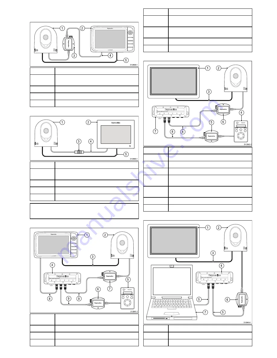
3.3 Typical systems
Example c / e Series system
D12839-1
3
2
1
4
5
1
Thermal camera.
2
c / e Series multifunction display (Integrated display and
controller).
3
Power over Ethernet (PoE) injector.
4
RayNet to SeaTalk
hs
cable.
5
Video cable.
Example gS Series system
3
4
D12840-1
2
1
5
1
Thermal camera.
2
gS Series multifunction display (Integrated display and
controller).
3
Ethernet coupler.
4
RayNet to SeaTalk
hs
cable.
5
Video cable.
Note:
When connected directly to a gS Series multifunction
display the thermal camera is supplied with power over
ethernet from the display.
Example System with JCU
D12841-1
7
9
8
2
1
3
5
4
6
9
1
c / e Series multifunction display (Integrated display and
controller).
2
Thermal camera.
3
Video input cable.
4
Network switch.
5
JCU (Optional controller).
6
Power over Ethernet (PoE) injector (Required to supply
power to the JCU).
7
Power over Ethernet (PoE) injector (Required to supply
power to the thermal camera).
8
RayNet cable.
9
RayNet to SeaTalk
hs
cable.
Example system with JCU and display
D12842-1
6
7
8
2
1
3
4
5
8
1
Video Display (Display only).
2
Thermal camera.
3
Video input cable.
4
JCU (Required Controller).
5
Power over Ethernet (PoE) injector (Required to supply
power to the JCU).
6
Power over Ethernet (PoE) injector (Required to supply
power to the thermal camera).
7
Network switch.
8
RayNet to SeaTalk
hs
cable.
Example system with PC controller and display
D12843-1
2
6
5
1
7
5
3
4
1
Video Display (Display only).
2
Thermal camera.
3
Video input cable.
Planning the installation


