4.2 Connections overview
Use the following information to help you identify the
connections on your product.
Connector
Connector
panel label Connects to:
Suitable
cables
Network
RayNet
network or
device.
Refer to the
Chapter
10
Spares
and
accessories
section.
Power
12 V / 24 V
power supply.
Supplied with
your product.
Transducer
Compatible
transducer.
Supplied
with the
transducer.
Making connections
Follow the steps below to connect the cable(s) to
your product.
1. Ensure that the vessel's power supply is switched
off.
2. Ensure that the device being connected to the
unit has been installed in accordance with the
installation instructions supplied with that device.
3. Ensuring correct orientation, push the cable
connector fully onto the corresponding connector
on the unit.
4. Turn the locking collar clockwise to secure the
cable.
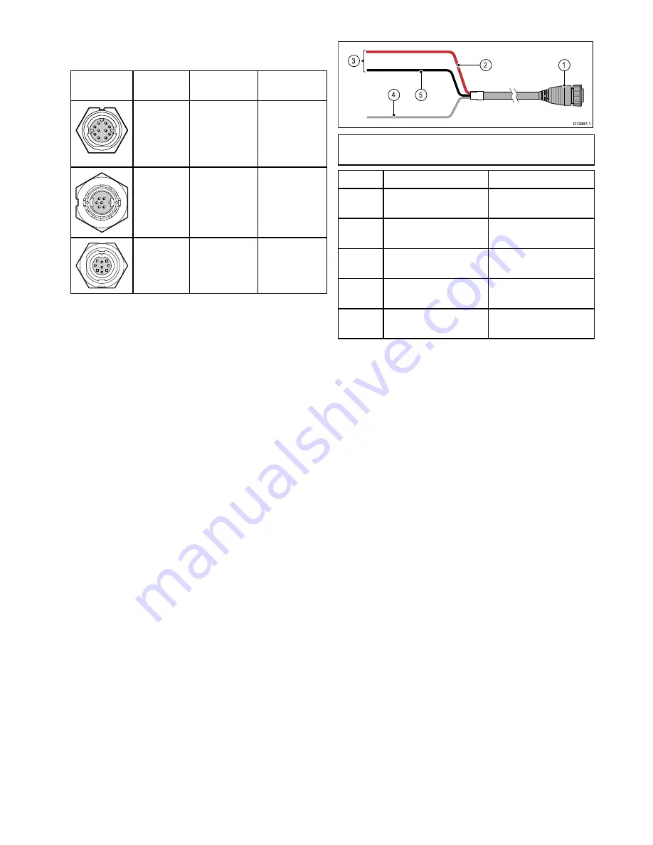
4.3 Power connection
5
4
3
D12947-1
1
2
Note:
For clarity, only the power-related cables
are shown in the illustration above.
Item
Description
Connects to:
1
Power cable.
Product’s power
connector.
2
Red cable (positive)
Power supply’s positive
terminal.
3
Connection to 12 V /
24 V power supply.
Power supply.
4
Shield (drain) wire
Must be connected to
RF ground point.
5
Black cable (negative)
Power supply’s negative
terminal.
Power cable extension
The product is supplied with a power cable, which
can be extended if required.
• The power cable for each unit in your system
should be run as a separate, single length of
2-wire cable from the unit to the vessel's battery or
distribution panel.
• Raymarine recommends a
minimum
wire gauge
of 18AWG (0.82 mm
2
) for any length of cable
extension.
• Regardless of the length of the cable extension,
any cable used should be capable of achieving a
minimum
voltage at the unit of 10.8 V with a fully
flat battery at 11 V.
Power distribution
Raymarine recommends that all power connections
are made via a distribution panel.
• All equipment must be powered from a breaker or
switch, with appropriate circuit protection.
• Refer to the
Breakers, fuses and circuit protection
section for specific fuse and thermal breaker
ratings for this product.
Breakers, fuses and circuit protection
The information below is provided as guidance
to help protect your product. The example
illustrations provided are for common vessel power
arrangements, if you are unsure how to provide the
correct level of protection then please consult a
Raymarine authorized dealer for support.
Cables and connections


