background image

PowerPlus System 100-3-1U 

    INSTALLATION INSTRUCTION & OPERATION MANUAL

www.raycap.com

(

320-1398) QRC | Rev.A


 © Raycap | All rights reserved.

Page 24 of 34

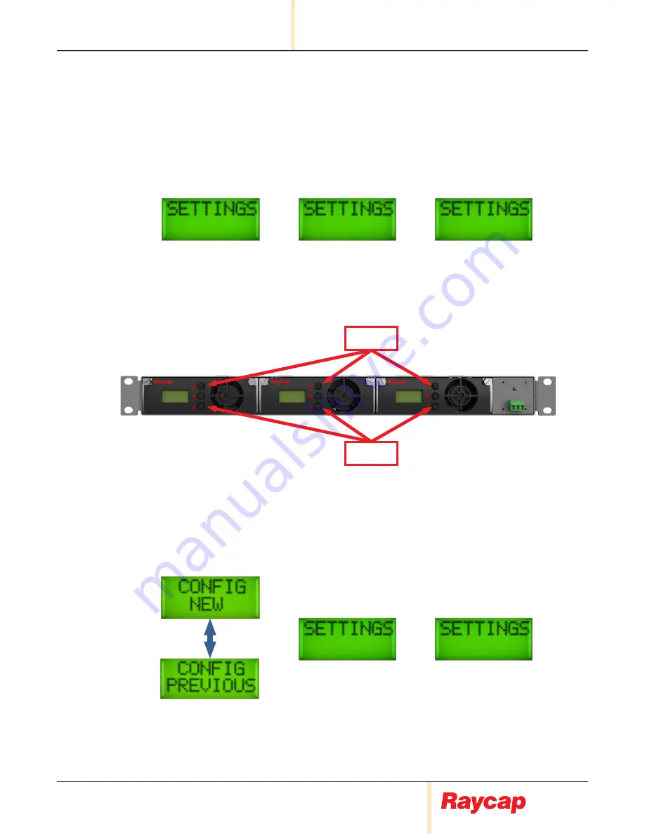
11.  Live Settings Menu 

11.1  

Live Settings


• 

The 

live settings

 menu is displayed by pressing ‘

UP

’ and ‘

DOWN

’ buttons of the primary module 

simultaneously for more than 3 seconds while the system is running in the main operation cycle. In 
this menu the modules in each slot are displaying “

SETTINGS

” message.

• 

The 

Primary module

 is selected by pressing the ‘

ENTER

’ button of any module (e.g. Slot 1 module). 

This module will become the primary module and the other modules will be configured as secondary 

modules.

Slot 1

Slot 2

Slot 3

UP

DOWN

11.2  

New/Previous Configuration Selection


• 

Next step is the 

New/Previous Configuration

 selection. The configuration selection is changed by 

pressing the ‘

UP

’ or ‘

DOWN

’ buttons of the primary module. The selection is applied by pressing the 

ENTER

’ button of the Primary module. 

Slot 2

Slot 3

Up/Down

Slot 1

Primary

Содержание PowerPlus System 100-3-1U Series

Страница 1: ...www raycap com INSTALLATION INSTRUCTION OPERATION MANUAL PowerPlus System 100 3 1U INSTALLATION INSTRUCTION OPERATION MANUAL PowerPlus System 100 3 1U Series 100 3 1U 3 100 3 1U 2 ...

Страница 2: ......

Страница 3: ...tion 5 5 3 System Topology 6 5 4 Installation Configurations 7 5 5 Module Configurations 8 12 6 System Management 13 6 1 Modules 13 6 2 Module Failure 14 6 3 Primary Failure 14 7 Modules 15 7 1 Module Replacement 15 7 2 Cold Module Replacement 16 7 3 Hot Module Replacement 16 7 4 Hot Module Replacement Invalid Module Installation 16 8 Module Settings 17 8 1 Settings Menus 17 8 2 Initial Settings M...

Страница 4: ...e all reasonable efforts to ensure that the instructions contained in this document are adequate and free of material errors and omissions Raycap will if deemed necessary explain issues which may not be covered by this document The contents of this document are subject to revision without notice due to continued progress in methodology design and manufacturing Raycap shall have no liability for an...

Страница 5: ...RH and BBU PowerPlus is Raycap s solution for an intelligent and dynamic power transmission to the RRH units of a DAS Telecommunication site PowerPlus is a system installed at the PSU output that increases the voltage at the base of a cellular site to compensate the voltage drop on the DC power cables that provide power to the RRHs 3 0 Package Contents 1 each 1 1U PowerPlus System 1 Rack Extension...

Страница 6: ... All rights reserved Page 4 of 34 4 Mounting 4 1 Select a suitable position for the installation of the unit You will need 1U vertical space 4 2 The unit ships with a Rack Extension Kit to mount into a 23 rack 4 4 Mount the unit on the rack 4 5 Release the 4 push pins and remove touch guard as shown below 1U ...

Страница 7: ...while the battery voltage decreases due to discharging Then the radio can operate for a longer period on the battery supply 5 2 Modes of Operation The PowerPlus 100 3 1U system is composed of a mounting rack and up to three pluggable modules The PowerPlus 100 3 1U system may operate in one of two modes The Single Mode and the Parallel Mode The voltage output of each module may be connected to an i...

Страница 8: ...tem 100 3 1U INSTALLATION INSTRUCTION OPERATION MANUAL www raycap com 320 1398 QRC Rev A Raycap All rights reserved Page 6 of 34 5 3 System Topology 48VDC OUT 1 48VDC OUT 2 48VDC OUT 3 48VDC IN RTN OUT RTN IN GROUND ...

Страница 9: ...1U www raycap com Raycap All rights reserved 320 1398 QRC Rev A Page 7 of 34 5 4 Installation Configurations PowerPlus 100 3 1U system configurations SINGLE 48VDC OUT 3 48VDC OUT 2 48VDC OUT 1 RTN OUT 48VDC RTN GND DC PS PARALLEL 48VDC OUT RTN OUT DC PS 48VDC RTN GND ...

Страница 10: ...SNDC 7771 PF 48 RTMDC 4983 RM 48 48V OUT 48V IN Return OUT Return IN GROUND Power Plus Configuration 1 For applications requiring 100 AMPS or less 100 AMP Breaker Recommended Lugs For 2 Gauge Use Panduit LCD2 14 Q for Input Output For 6 Gauge Use Panduit LCD6 14A for Ground USE ONLY 2 GAUGE COPPER WIRE FOR INPUT OUTPUT 100 AMP Module Installed Trunk to Upper OVP Use 6 gauge copper wire for ground ...

Страница 11: ...urn OUT Return IN GROUND RTMDC 5634 PF 48 RNSNDC 7771 PF 48 RTMDC 4983 RM 48 Configuration 2 For applications requiring 200 AMPS or less 200 AMP Breaker Recommended Lugs For 2 Gauge Use Panduit LCD2 14 Q for Input Output For 6 Gauge Use Panduit LCD6 14A for Ground Use 6 gauge copper wire for ground USE ONLY 2 GAUGE COPPER WIRE FOR INPUT OUTPUT 100 AMP Module Installed 100 AMP Module Installed Trun...

Страница 12: ... 48 RNSNDC 7771 PF 48 RTMDC 4983 RM 48 200 AMP Breaker Recommended Lugs For 2 Gauge Use Panduit LCD2 14 Q for Input Output For 6 Gauge Use Panduit LCD6 14A for Ground USE ONLY 2 GAUGE COPPER WIRE FOR INPUT OUTPUT Configuration 3 For applications requiring 200 AMPS or less 100 AMP Module Installed 100 AMP Module Installed Trunk to Upper OVP 5 7 2 Module in Parallel Configuration Use 6 gauge copper ...

Страница 13: ... PF 48 RTMDC 4983 RM 48 Configuration 4 For applications requiring 300 AMPS or less 300 AMP Breaker USE ONLY 1 Ø GAUGE COPPER WIRE FOR INPUT USE ONLY 2 GAUGE COPPER WIRE FOR OUTPUT 100 AMP Module Installed 100 AMP Module Installed 100 AMP Module Installed Trunk to Upper OVP Use 6 gauge copper wire for ground Recommended Lugs For 1 O Gauge Use Panduit LCD1 O 14A X for Input For 2 Gauge Use Panduit ...

Страница 14: ...1 PF 48 RTMDC 4983 RM 48 Configuration 5 For applications requiring 300 AMPS or less 300 AMP Breaker Recommended Lugs For 1 O Gauge Use Panduit LCD1 O 14A X for Input For 2 Gauge Use Panduit LCD2 14A Q for Output For 6 Gauge Use Panduit LCD6 14A L for Ground USE ONLY 1 Ø GAUGE COPPER WIRE FOR INPUT USE ONLY 2 GAUGE COPPER WIRE FOR OUTPUT 100 AMP Module Installed 100 AMP Module Installed 100 AMP Mo...

Страница 15: ...e response to this event When the primary module fails another secondary module will overtake control of the system as primary All modules in single mode will display the input and output voltage of the system The primary module is indicated by an P character which is located at the end of the input voltage value first line of the display The primary module in the parallel mode will display the in...

Страница 16: ...to the new secondary module The alarm will be reset after pressing the ENTER button on the primary module for more than 3 seconds 6 3 Primary Failure When the primary module fails another secondary module will overtake the role of primary and raise an alarm The front panel s LED will change from GREEN to RED the remote contact will change to Failed and the new primary module will display the Prima...

Страница 17: ...MANUAL PowerPlus System 100 3 1U www raycap com Raycap All rights reserved 320 1398 QRC Rev A Page 15 of 34 7 Modules 7 1 Module Replacement Unscrew the thumb screws on both sides of module Release the side levers out Pull out the device ...

Страница 18: ...t point of the initial settings menu 7 3 Hot Module Replacement Hot Module Replacement is the replacement of a module when the system is running Every module stores the settings of all other modules in the system When a module fails primary module or secondary module failure it must be replaced The replacement may occur while the system is running The settings of the replaced module will be transf...

Страница 19: ... live settings menu is enabled when the UP and DOWN buttons of the Primary module are pressed simultaneously for more than 3 seconds The initial settings menu and the live settings menu are very simple menus 8 2 Initial Settings Menu The initial settings menu will appear when the system detects conflicting setting during system boot or at initial power up Each module will display the SETTINGS mess...

Страница 20: ...he secondary modules also are displaying the SETTINGS message 9 Parallel Mode Settings 9 1 Initial Settings Menu Parallel Mode System Units Selection In Parallel Mode selection the next step is the System Units selection There are two types of system units Imperial and Metric The system units are changed by pressing the UP or DOWN buttons of the primary module The selection is applied by pressing ...

Страница 21: ...Up Down Up Down Slot 1 Primary Imperial Slot 1 Primary Metric Slot 2 Slot 3 9 3 Initial Settings Menu Parallel Mode System Units Selection Cable Cross Section Selection Cable Length Selection Next is the Cable Length selection The range of cable length is 0m 999m or 0ft 999ft depending on system units selection The cable length is changed by pressing the UP or DOWN buttons of the primary module Th...

Страница 22: ... cycle Slot 1 Primary Main Parallel Mode Operation Slot 1 Primary Slot 2 Slot 2 Slot 3 Slot 3 9 4 Initial Settings Menu Parallel Mode System Units Selection Cable Cross Section Selection Cable Length Selection Top Voltage Target Selection The next step is the Top Voltage Target selection The range of this parameter is from 60V to 54V and could be selected by pressing the UP and DOWN buttons of the...

Страница 23: ...TINGS message because they are waiting for their unique settings due to independent operation The buttons for each secondary module is enabled in order to input its new settings Up Down Slot 1 Primary Slot 2 Slot 3 10 2 Initial Settings Menu Single Mode System Units Selection Cable Cross Section Selection The next step is the Cable Cross Section selection There are many standard cross section type...

Страница 24: ...us 100 3 1U system to the radio input The system then calculates 2X this cable length to account for the return and 48V cable runs Up Down Up Down 1ft 1m Slot 1 Primary Imperial Slot 1 Primary Metric Slot 2 Slot 3 10 4 Initial Settings Menu Parallel Mode System Units Selection Cable Cross Section Selection Cable Length Selection Top Voltage Target Selection The next step is the Top Voltage Target ...

Страница 25: ...rts the single mode operation cycle Slot 1 Primary Main Single Mode Operation Slot 1 Primary Slot 2 Slot 2 Slot 3 Slot 3 10 5 Initial Settings Menu Single Mode System Units Selection Cable Cross Section Selection Cable Length Selection Top Voltage Target Next Module Setting The top voltage target is the final step of the initial settings menu Next the primary will display the calculated cable resi...

Страница 26: ...e modules in each slot are displaying SETTINGS message The Primary module is selected by pressing the ENTER button of any module e g Slot 1 module This module will become the primary module and the other modules will be configured as secondary modules Slot 1 Slot 2 Slot 3 UP DOWN 11 2 New Previous Configuration Selection Next step is the New Previous Configuration selection The configuration selec...

Страница 27: ... is the New Previous Configuration selection and the next step for the primary is the mode selection From this point the modules can be configured independently with the same proceeding steps as the initial settings menu Slot 1 Primary Slot 1 Primary Slot 2 Slot 2 Slot 3 Slot 3 11 3 New Previous Configuration Selection Previous Configuration in Parallel Mode If previous configuration is selected a...

Страница 28: ... 3 Slot 3 Initial Settings 12 Bus Bar 12 1 Bus Bar Detection After the completion of the settings the system will sense if the bas bus bar is connected on the rear output terminals If the system is in parallel mode and the bus bar is not installed the system will display PLACE BUS BAR message A bus bar must be connected when parallel mode is selected If the system is in single mode and the bus bar...

Страница 29: ...he System Management section of this document 13 Alarms 13 1 Front Panel LED and Remote Contact Whenever an abnormal condition occurs the system will raise an alarm The front panel s LED will change from GREEN to RED and the remote contact will change to failed The maximum switching current of the remote contact is 2A Alarm LED Green Red Remote Contact Alarm Alarm Condition Common Alarm Condition ...

Страница 30: ...dary and will raise the module failure alarm In parallel mode when the current of a secondary is above the maximum current 110A for more than 3 seconds the primary isolates the overloaded secondary all module outputs are bypassed The secondary will display HIGH CURRENT message The primary will detect the stopped secondary and raise module failure alarm In any configuration mode parallel single whe...

Страница 31: ... HIGH message when this condition remains for more than 3 seconds The alarm is cleared when the input voltage decreases to normal level 13 6 Extra Low Input Voltage In any configuration parallel single when the input voltage of the system is below 38V for more than 200msec then the master turn the system in bypass mode until the input voltage increase in normal levels All modules of the system wil...

Страница 32: ...ure of a secondary is above the maximum temperature 120ºC for more than 3 seconds the secondary stops the module output is bypassed The secondary will display a HIGH TEMP message The primary detects the stopped secondary and will raise a module failure alarm In any configuration mode parallel single when the temperature of a primary is above the maximum temperature 120ºC for more than 3 seconds th...

Страница 33: ...urn the system in bypass mode until the temperature increase in normal levels 13 11 Module DC DC Converter Communication Failure In case that there is a communication failure between module and internal DC DC converter then the module will be halted and will display a DC DC COM FAIL message 13 10 Module DC DC Converter Failure When there is a sort circuit at the output of a module for more than 20...

Страница 34: ...PowerPlus System 100 3 1U INSTALLATION INSTRUCTION OPERATION MANUAL www raycap com 320 1398 QRC Rev A Raycap All rights reserved Page 32 of 34 Notes ...

Страница 35: ......

Страница 36: ...PowerPlus System 100 3 1U INSTALLATION INSTRUCTION OPERATION MANUAL www raycap com 320 1398 QRC Rev A Raycap All rights reserved Page 34 of 34 ...

Отзывы: