22
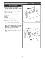
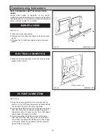
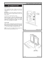
SEE FIG.25 & 26
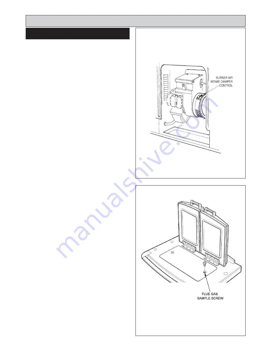
The air control of the burner is factory pre-set, however
small adjustments may be necessary to suit the site
conditions.
IMPORTANT:
Ensure that the bottom louvred plinth is in
place during combustion setting procedures and the outer
door is closed.
Turn burner on. Check flue fan is running.
After 15 minutes lift up the R.H. insulating cover and
remove the counter sunk screw and insert the sensing
end of a portable indicator to check the CO
2
(Carbon
Dioxide) level. Adjust the burner air intake until a reading
of 11.0 CO
2
is recorded on the indicator.
Check Smoke
Remove the CO
2
sampling tube and using the same hole
for flue sampling insert the sensing end of a Baccarach
Smoke Pump and check that the smoke does not exceed
0 - 1 on the scale. Replace the countersunk screw.
NOTE:
Ensure that the Hotplate is fitted correctly as this
forms part of the cooker combustion circuit.
Commissioning Instructions
SET COMBUSTION AIR
FIG. 25
FIG. 26
DESN 511429 A
DESN 514111
Содержание XT- Oil
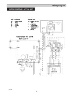
Страница 24: ...24 Wiring Diagram FIG 27 WIRING DIAGRAM APPLIANCE...
Страница 26: ...26...
Страница 27: ...27...

