


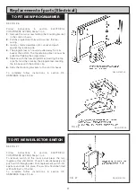


SEE FIG. 21
Follow instructions in section ELECTRICAL
COMPONENT ACCESS, Steps 1 to 6.
1.
Undo the two screws on the front of the chassis
which hold the thermostat in place.
2.
Remove the two push on connectors from back of
thermostat.
3.
Replace thermostat. Take care to push thermostat
phial correctly into the pocket provided. The
thermostat should be mounted with tag P at the
bottom.
4.
Re-connect push on connector wires. The RED wire to
P and BLACK wire to 2.
To complete follow instructions in section RE-ASSEMBLE
Steps 1 to 6.
Follow instructions in section ELECTRICAL COMPONENT
ACCESS, Steps 1 to 6.
1.
Undo the two screws on the front of the chassis
which hold the thermostat in place.
2.
Remove the three push on connectors from back of
thermostat.
3.
Replace thermostat. The thermostat should be
mounted with tag P at the right hand side (looking
from back). Take care to push thermostat phial
correctly into the pocket provided.
4.
Re-connect push on connector wires. The white wire
from the pump PL to P, the other WHITE wire to 2 and
the RED to 1.
To complete follow instructions in section RE-ASSEMBLE
Steps 1 to 6.
SEE FIG. 23
Follow instructions in section ELECTRICAL COMPONENT
ACCESS, Steps 1 to 6.
1.
Remove the two push on connectors from the
thermostat.
2.
Undo the two screws and nuts which hold the
thermostat in place.
3.
Replace thermostat. Take care to push thermostat
phial correctly into pocket provided.
4.
Re-connect push on connector wires.
To complete follow instructions in section RE-ASSEMBLE
Steps 1 to 6.
Replacement of parts (Electrical)
TO FIT NEW BOILER CONTROL
THERMOSTAT
TO FIT NEW BOILER PUMP
OVERRUN THERMOSTAT
15
FIG. 21
FIG. 22
FIG. 23
DESN 510546 A
DESN 510547 A
DESN 511244
TO FIT NEW COOKER SAFETY
OVERHEAT THERMOSTAT
Содержание Heatranger 480GB
Страница 15: ...Replacement of parts Electrical FIG 20 DESN 511140 14...
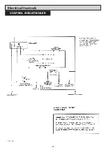
Страница 23: ...Electrical Controls 22 CONTROL CIRCUIT BOILER FIG 30...
Страница 24: ...Electrical Controls 23 CONTROL CIRCUIT COOKER FIG 31...
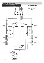
Страница 25: ...Electrical Controls 24 WIRING DIAGRAM BURNER ONLY FIG 32...
Страница 26: ...25 WIRING DIAGRAM APPLIANCE Electrical Controls FIG 33...
Страница 30: ...29...
Страница 31: ...30...
Страница 32: ......
Страница 33: ......


