


SEE FIG. 15
Follow instructions in sections BURNER ACCESS, Steps
1 to 3, BURNER REMOVAL, Steps 1 to 6 and
DISMANTLE BURNERS, Steps 1 to 2.
1.
Remove securing nut and disconnect H.T. lead from
ignition electrode.
2.
Remove control box, by inserting screwdriver as
directed on control box.
3.
Disconnect live wiring to terminal 7.
4.
Disconnect neutral wiring.
5.
Disconnect earth wiring.
6.
Remove 2 ignitor securing nuts and bolts in reverse
order.
7.
Remove ignitor.
8.
Fit new ignitor, re-assemble in reverse order.
SEE FIG. 16
Follow instructions in sections BURNER ACCESS, Steps
1 to 3 and BURNER REMOVAL, Steps 1 to 3.
1.
Remove control boxes.
2.
Break 2 gas pipe connections.
3.
Lower gas valve assembly forward.
SEE FIG. 17
1.
Remove 4 gas valve securing screws (gas valve to
manifold).
2.
Remove valve plug, 1 screw.
3.
Remove appropriate pipework from valve. Fit to new
valve.
4.
Re-assemble gas valve in reverse order.
NOTE: ENSURE ‘O’ RING IS LOCATED CORRECTLY IN
MANIFOLD.
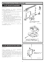
Replacement of parts (Burner)
GAS VALVE ACCESS
GAS VALVE REPLACEMENT
FIG. 15
FIG. 16
FIG. 17
DESN 511137
DESN 511138
DESN 511139
IGNITOR
12
Содержание Heatranger 480GB
Страница 15: ...Replacement of parts Electrical FIG 20 DESN 511140 14...
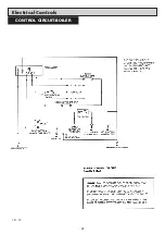
Страница 23: ...Electrical Controls 22 CONTROL CIRCUIT BOILER FIG 30...
Страница 24: ...Electrical Controls 23 CONTROL CIRCUIT COOKER FIG 31...
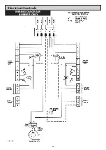
Страница 25: ...Electrical Controls 24 WIRING DIAGRAM BURNER ONLY FIG 32...
Страница 26: ...25 WIRING DIAGRAM APPLIANCE Electrical Controls FIG 33...
Страница 30: ...29...
Страница 31: ...30...
Страница 32: ......
Страница 33: ......