CHAPTER 2 INSTALLING and SETTING UP THE UNIT
EQUIPMENT SETUP
The RFMOW V2 enclosure contains the necessary hardware to interface the ports of a Monitor, Keyboard,
Mouse, Secure Voice Unit, KIV carrier, and satellite modem. All interface connections to external equipment
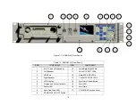
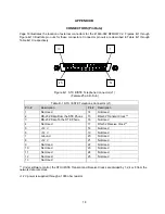
are mounted on the rear panel. See the rear panel diagram on page 18 for the location of the connectors
mentioned below.
Warning: This device has High Voltage. Make sure to disconnect the power cord before servicing the unit.
Failure to do so may result in physical injury due to electrical shock.
J1 – Secure Voice Interface
•
The Unit supports full duplex RS-232 specification signals for transmit and receive data on J1. In
addition, transmit and receive clocks are provided from the network clock frequency divided by 1, 2, 4 or
8 (the division is under software control).
J2 –Modem Data Port
•
The Unit supports full duplex RS-422 specification signals for transmit and receive data on J2. In
addition, the Unit expects to receive network transmit and receive clocks from the modem with RS-422
specification signals.
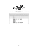
J4 – Modem Control Data Port (PC) (This connector is only used in “IU Mode”.)
•
The Unit supports full duplex RS-232 specification signals for transmit and receive modem control
signals on J4. This connector, along with J6, is for connecting an external PC/controller. In addition, the
Alarm Horn and the COMSEC / Secure Voice data source switch (“A / B” switch) are controlled by RS-
232 specification signals on this connector.
J5 – Hardware Control Bus Port (Modem)
•
The Unit supports full duplex RS-485 specification signals for transmit and receive modem control
signals on J5. The port is designed as a 4-wire port (separate transmit and receive wires) but may be
connected as a 2-wire port (transmit and receive wires connected together), since the transmit buffer is
tri-stated when it is not transmitting.
J6 – Primary Data Port (PC) (This connector is only used in “IU Mode”.)
•
The Unit passes signals on this port directly to the COMSEC device Red connector. This connector,
along with J4, is for connecting an external PC/controller.
J7 – DC Power
•
The Unit su12 VDC power to this connector for external use. Current drain is limited to 1 Amp
total.
6
Содержание RFMOW V2
Страница 10: ...This page left blank intentionally 8...


