APPENDIX B
CONNECTORS (Pin Outs)
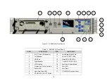
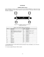
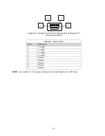
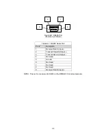
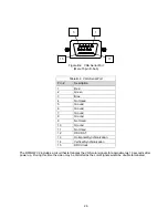
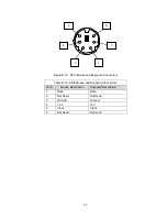
Page 18 illustrates the location of external connectors for the 41800-002 RFMOW V2. Figures B-1 through
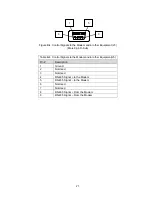
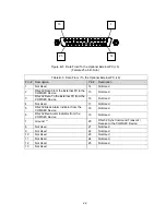
Figure B-10 illustrate pin outs for these connectors. Connector pin outs are described in Table B-1 through
Table B-10, respectively.
25
14
13
1
Figure B-1 STU III/STE Telephone Connector (J1)
(Female 25 pin D-Sub)
Table B-1 STU III/STE Telephone Connector (J1)
Pin #
Description
Pin #
Description
1
Not Used
14
Not Used
2
RS-232 Data From the STE Phone
15
RS-232 Transmit Clock **
3
RS-232 Data To the STE Phone
16
Not Used
4
Not Used
17
RS-232 Receive Clock **
5
+12 V
18
Not Used
6
+12 V
19
Not Used
7 Ground
20
Not
Used
8
+12 V
21
Not Used
9
Not Used
22
Not Used
10
Not Used
23
Not Used
11
Not Used
24
Not Used
12
Not Used
25
Not Used
13 Not
Used
** Under software control, the STU III/STE Transmit and Receive Clocks are divided by 1,2,4 or 8 from the
network data rate clock.
+12 V power is supplied through a 1000 ohm resistor.
18
Содержание RFMOW V2
Страница 10: ...This page left blank intentionally 8...


