EN
Page 24 of 91
INSTRUCTION, USE AND
MAINTENANCE MANUAL
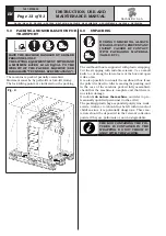
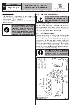
5. Mount the card (
Fig. 25 ref. 2
)
.
6. Connect ultrasound Run-out cable plug (
Fig. 25
ref. 1
) to the electronic card (
Fig. 25 ref. 2
), as
shown in
25
(blue
ref. 4 cable,
brown
ref. 5
cable and
black
ref. 6 cable)
. Connect the ultra-
sound Run-out card (
Fig. 25 ref. 2
) to the wheel
balancer main card, using the provided cable JP18
(
Fig. 25 ref. 3
). Carry out the connection as shown
in
Fig. 25
.
Fig. 25
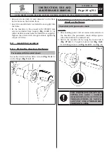
7. Fix the cables with clamps not to let them hinder
the ordinary operation of the machine.
8. Mount wheel balancer protection guard again.
FOR THE CONNECTIONS, REFER
TO WIRING DIAGRAMS.
9.2.11 Fitting of ultrasound Run-out with sup-
port (optional)
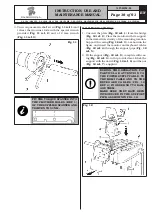
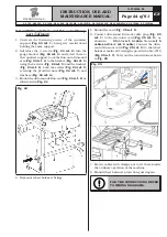
1. Unscrew the fastening screws of the equalizer
support (
Fig. 24 ref. 1
), being very careful about
holding the same support.
2. Introduce the 3 screws (
Fig. 24 ref. 2
) into the
gauge bracket (
Fig. 24 ref. 3
) and screw them to
the equalizer support. Lock the Run-out ultrasound
arm (
Fig. 24 ref. 4
) to the bracket (
Fig. 24 ref. 3
)
using the 2 screws (
Fig. 24 ref. 5
) and the washers
(
Fig. 24 ref. 6
). Lock the screws (
Fig. 24 ref. 5
)
screwing the provided nuts (
Fig. 24 ref. 7
) and
washers (
Fig. 24 ref. 6
).
3. Mount the ultrasounds Run-out (
Fig. 24 ref. 8
) as
illustrated in
Fig. 24
.
Fig. 24
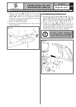
4. Demount wheel balancer bridge.
G3.150 - GP3.150 - G3.150S - GP3.150S - G3.150WS - GP3.150WS - G3.150WSPLUS - GP3.150WSPLUS - G3.150SA - G3.150WSA
RAVAGLIOLI S.p.A.
1297-M058-00

