


Rastergraf
Specifications 2-3
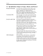
DVI-I Connector:
The DVI-I connector supplies both the digital DVI signals
and dual analog VGA. Rastergraf can supply an adapter
that allows a standard VGA cable to be connected to the
DVI-I connector. A breakout cable can split out the DVI
and the two VGA channels.
Composite Video Signal:
A jumper can be installed to select Sync-On-Green
operation on boot-up. The signal has the following
approximate values:
1 Volt peak to peak consisting of:
660 mV Reference White +
54 mV Reference Black +
286 mV Sync Level
Power-management:
With the proper software, the SM731 can power-down
unused functions.
Fuse Element:
The +5V supplied to the front panel connectors is protected
by a Positive Temperature Coefficient (PTC) resistor. It
resets automatically when an overload is removed.
PCI Bus Access:
Programmable Bus Address Registers (BARs) in the
SM731 map control and drawing engine registers, and
display memory through its 33/66 MHz PCI interface.
PCI Bus Usage:
32-bit, 33/66 MHz, J1/J2/Pn4
Important Note: The SM731 at 66 MHz can be marginal.
When using with the board at 66 MHZ on PMC-PCI or
PCM-CompactPCI carrier, you
MUST
use an active
version that has a local PCI-PCI bridge.
PCI bus Interrupts:
The SM731 can interrupt the PCI bus on the INTA line.
PCI Bus Master:
The SM731 can assume bus mastership of the PCI.
Bus Loading:
One PCI 2.1 compatible load
PCI Vendor ID:
Hardwired to 126Fh. Identify Silicon Motion as vendor.
PCI Device ID:
Hardwired to 0730h to identify the SM731 device. .
PCI Subsystem Vendor ID:
Powers up as 0x0000. Can be loaded by BIOS.
PCI Subsystem Device ID:
Powers up as 0x0000. Can be loaded by BIOS.
Содержание Duros
Страница 8: ......
Страница 13: ...Rastergraf General Information 1 1 Chapter 1 General Information...
Страница 40: ......
Страница 41: ...Rastergraf Specifications 2 1 Chapter 2 Specifications...
Страница 61: ...Rastergraf Connector Pinouts and Cable Information 3 1 Chapter 3 Connector Pinouts and Cable Information...
Страница 105: ...Rastergraf Installing Your Rastergraf Graphics Board 4 1 Chapter 4 Installing Your Rastergraf Graphics Board...
Страница 133: ...Rastergraf Programming On board Devices and Memories 5 1 Chapter 5 Programming On board Devices and Memories...
Страница 136: ...Rastergraf 5 4 Programming On board Devices and Memories...
Страница 137: ...Rastergraf Programming On board Devices and Memories 5 5...
Страница 138: ...Rastergraf 5 6 Programming On board Devices and Memories...
Страница 139: ...Rastergraf Programming On board Devices and Memories 5 7...
Страница 140: ...Rastergraf 5 8 Programming On board Devices and Memories...
Страница 141: ...Rastergraf Programming On board Devices and Memories 5 9...
Страница 142: ...Rastergraf 5 10 Programming On board Devices and Memories...
Страница 143: ...Rastergraf Programming On board Devices and Memories 5 11...
Страница 164: ......
Страница 165: ...Rastergraf Troubleshooting 6 1 Chapter 6 Troubleshooting...


