EN
9
10. INSTALLATION AND USE
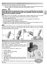
To install and use the cutting unit proceed as follows:
1) Fix the cutting unit directly on the motor body by means of two half rings and screw
them by means of two socket head screws (see pictures 4 and 5).
NOTE
The cutting unit can be installed in any position/angle: vertically, laterally and it can be turned
upside down. It is not necessary that the aluminium base touches the machine table.
2) Lay the material to be cut;
3) Connect the air pipe to the quick connection “A” (not supplied) (see picture 6);
4) Set the pressure gauge (option) to 6 bar;
5) Put the material on the cutting foot (see picture 7);
6) Adjust the front mobile protection according to the thickness of the material to be cut;
7) Enable the air remotely and carry out the cutting operation.
NOTE
Cutting unit FP120M can work in a fixed position (the material moves) or it can move forward
while the material is kept in the same position. Make sure the material to be cut is properly
stretched, preventing it from curling.
4
WARNING
Do not tighten the two socket head screws, so as to avoid that the two half rings
deform the motor. Consider that the motor has a diameter of 65 mm (see picture
4). In this case, warranty is not valid.
6
7
A
11. AIR PRESSURE GAUGE (OPTION)
8
The cutting unit must be necessarily supplied with
lubricated air with a pressure of 4-6 bar.
Rasor
®
offers, as option, a reduction unit filter with a
pressure gauge already calibrated with the quantity of
oil to be delivered.
The unit shown in picture 8 is made up of:
1 - pressure reducer;
2 - valve to drain the condensate;
3 - drip-feed oiler unit;
4 - oil tank;
5 - pressure gauge;
6 - condensate tank;
7 - pipe fitting to connect the quick connection to the network;
8 - pipe fitting to connect the quick connection to the
cutting unit.
For the use and maintenance read the instruction sheet supplied with
the filter.
5
1
2
3
4
6
7
8
5
Содержание FP120M
Страница 1: ...PNEUMATIC CUTTING UNIT USE MANUAL FP120M...


