Vector Solo 65kV Applicator - Maintenance
26
AH-08-02.6
NEEDLE / ELECTRODE
RESISTANCE TESTING
The electrical resistance of the needle/electrode
should be tested periodically (typically on a weekly
basis) or any time it is removed from the applicator.
To Test
1. Install the needle/electrode onto the front end
of an available needle shaft. Be sure that the
needle/electrode is completely seated for proper
contact between the metal shaft and the threaded
insert of the needle/electrode.
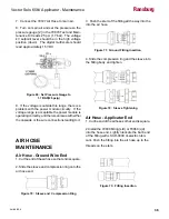
2. Using a VOM meter that will read 15 megohms
accurately, connect the first meter lead to the metal
needle shaft and the second lead to the needle/
electrode wire. The needle/electrode resistance
should be 14.5 to 19 megohms (nominal 15 meg-
ohms at 9 volts or 12 to 17 megohms at 1000
volts). Needle/electrodes outside these ranges
must be replaced.
Figure 23: Testing Resistive Electrode
BARREL REMOVAL
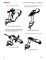
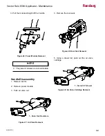
1. Remove air cap and fluid nozzle.
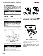
2. Remove two (2) screws with a 3mm Allen wrench
that hold the rear cover. Remove rear cover and
disconnect the connector.
Figure 24: Rear Cover Removal
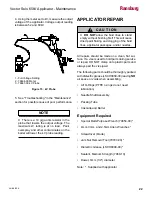
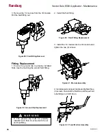
3. Remove the rear fluid adjustment bushing and
air valve and fluid needle return springs.
Figure 25: Fluid Adjust Bushing Removal
Ransburg


