background image

Vector Solo 65kV Applicator - Operation

17

AH-08-02.6

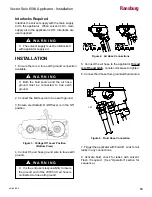
Figure 12:  Electrostatics Lever Off Position

FLUSHING / COLOR 

CHANGE PROCEDURE

1.  Turn electrostatic lever to Off position.

Figure 10:  Fan Pattern Size Adjustment

5.   Adjust  fan  pattern  size.    Counter-clockwise 

makes the pattern longer; clockwise makes the 

pattern shorter.  Full clockwise creates a small 

circular pattern.

6.  To change the spray pattern axis of fan atomizers 

from horizontal to vertical, loosen the air nozzle 

retaining ring, rotate the air cap clockwise to the 

desired position, and tighten the ring.

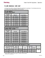
7. Use the "Fluid Nozzle Selection Chart and 

Air Cap/Fluid Nozzle Performance Chart" in the 

"Installation" section to select the proper air cap 

and fluid nozzle for the applications.

8. The applicator is shipped standard with a plug 

in the atomization air port.  If lower atomization 

air pressures are desired, a compensation valve 

is included with each applicator and can be used 

instead of the plug. The compensation valve 

(included separate with applicator) reduces the 

atomization air pressure approximately 0.2 bar 

(3 psig) per clockwise turn from the wide open  

position. To determine what pressure the applicator 

is set at, use the Air Cap Test Kit in  "Accessories" 

in the  "Parts Identification" section.

Figure 11: Compensation Valve - 

             Full Open Position

79727

Hose Length

30m
20m
15m
10m

Table I - Pressure at Regulator

Pressure At

 Wall Regulator Gauge

5.9 bar (85 psig)
4.8 bar (70 psig)
4.5 bar (65 psig)
4.1 bar (60 psig)

Ransburg

Содержание vector solo 79965 solventborne RS70-AS

Страница 1: ... APPLICATOR TM Ransburg MODEL 79965 Solventborne RS70 AS IMPORTANT Before using this equipment carefullyread SAFETYPRECAUTIONS starting on page 1 and all instructions in this manual Keep this Service Manual for future reference Service Manual Price 50 00 U S ...
Страница 2: ...NOTE This manual has been changed from revision AH 08 02 5 to revision AH 08 02 6 Reasons for this change are noted under Manual Change Summary inside the back cover of this manual AH 08 02 6 Ransburg ...

Страница 3: ...PRECAUTIONS 1 HAZARDS SAFEGUARDS 2 4 PAGE INTRODUCTION 9 12 CONTENTS GENERAL DESCRIPTION 9 79965 VECTOR SOLO 65KV SOLVENTBORNE SPECIFICATIONS 10 VECTOR SOLO 65KV SOLVENTBORNE ELECTROSTATIC SPRAY APPLICATOR 11 VECTOR SOLO 65KV TYPICAL SOLVENTBORNE INSTALLATION 12 Vector Solo 65kV Applicator Contents INSTALLATION 13 14 79965 SOLO 65KV SOLVENTBORNE INSTALLATION 13 14 INSTALLATION 14 Continued On Next...

Страница 4: ...44 FLUID TUBE SELECTION 44 TRIGGER SELECTION 44 SPRAY SELECTION 44 FLUID HOSE SELECTION 45 79911 00 79911 01 NEEDLE SHAFT PARTS LIST 45 46 POWER MODULE REPLACEABLE PARTS PARTS LIST 46 ACCESSORIES PARTS LIST 47 50 PARTS COMPARISON TRANS TECH ATOMIZATION PARTS LIST 51 VECTOR SOLO RECOMMENDED SPARE PARTS 52 WARRANTY POLICIES 54 LIMITED WARRANTY 54 CONTENTS Cont Vector Solo 65kV Applicator Contents AH...

Страница 5: ...installationdrawings and appropriate Ransburg equipment manuals to reconcile such differences Carefulstudyandcontinueduseofthismanualwill provide a better understanding of the equipment and process resulting in more efficient operation longer trouble free service and faster easier trou bleshooting If you do not have the manuals and safetyliteratureforyourRansburgsystem contact your local Ransburg ...

Страница 6: ...leaning Those used for equipment flushing should have flash points equal to or higher than those of the coating material Those solvents used for cleaning must have a flash point at minimum of 5 C 9 F greater than the ambient temperature It is the end users re sponsibility to insure this condition is met Spray booth ventilation must be kept at the rates requiredbylocaland orcountrycodes Inaddition ...

Страница 7: ...olent and lead to an equipment explosion Sprayapplicatorsrequirethataluminuminletfittings bereplacedwithstainlesssteel See Accessories in the Parts Identification section Aluminum is widely used in other spray application equipment such as material pumps regulators valves etc Check all other equipment items before use and make sure they can also be used safely with these solvents Read the label or...

Страница 8: ...76 RE GARDING OPERATOR GROUNDING OR SPE CIFIC COUNTRY SAFETY CODE B Parts being sprayed Resistance between the part and a grounded conveyor must not exceed 1 megohm C Every metal and conductive object in the spray area This includes the booth parts hangers fire extinguishers conductive flooring etc Grounded conductive flooring must be provided in the spray area Turn off voltage at the power module...

Страница 9: ...be fitted by suitably trained personnel in accordance with the manufacturer s documentation 8 The certification of this equipment relies upon the following materials used in its construction If the equipment is likely to come into contact with aggressivesubstances thenitistheresponsibility oftheusertotakesuitableprecautionsthatprevent itfrombeingadverselyaffected thusensuringthat the type of prote...

Страница 10: ... ciated Ransburg 79727 XX Air Hose Assembly It is the end users responsibility to insure the air hose is properly grounded to true earth ground Product Marking II 2 G Ex Specific marking of explosive protection II Equipment Group hazardous area characteristics 2 Equipment Category G Typeofexplosiveatmosphere gases vapors or mists EEx0 24mJ TheVector Solo79965 Applicators aresuitableforuseinmanuals...

Страница 11: ...Vector Solo 65kV Applicator Atex FM 7 AH 08 02 6 Ransburg ...

Страница 12: ...EMBLY 15 METER 49 PART NUMBER 79727 16 7 FOR QD AIR HOSE ASSEMBLY 20 METER 66 PART NUMBER 79727 21 8 FOR QD AIR HOSE ASSEMBLY 30 METER 99 PART NUMBER 79727 31 OPTION C DESIGNATIONS TRIGGER TYPE 2 FOR TWO FINGER TRIGGER PART NUMBER 79787 00 OPTION B DESIGNATIONS FLUID INLET TUBE 1 FOR STANDARD FLUID TUBE 093 ID PART NUMBER 79878 01 2 FOR COILED FLUID TUBE 125 ID PART NUMBER 79871 00 3 FOR FLUID TUB...

Страница 13: ...les are attracted to and deposited on the target object The forces between the charged particles and the grounded target are sufficient to turn most normal overspray around and deposit it on the back surface of the target Therefore ahighpercentageofthecoating is deposited on the target One of the many features of the Vector Solo ap plicator system is that the electrical energy which is available f...

Страница 14: ...deliver The maximum spray volume that can be effectively atomized depends on fluid rheolo gy spray technology and finish quality required Applicator Length 257mm 10 1 inches Weight 834 grams 29 4 oz Hose 79727 XX Lengths Std 10m 15m 20m and 30m Atomizer Nozzle Assembly Std 79374 65 79377 44 1 4mm Operating Voltage 65kV DC maximum Current Output 130 microamperes maximum Paint Resistance 1 MW to Use...

Страница 15: ...el Replaceable Hook Fan Air Adjustment Fluid Needle Travel Adjustment Fluid Hose Connection Air Inlet Connection VECTOR SOLO 65KV SOLVENTBORNE ELECTROSTATIC SPRAY APPLICATOR 8 9 10 11 12 13 No Description kV Setpoint Switch Voltage On Off Indicator Light Trigger Turbine Air Exhaust Voltage On Off Lever Power Module 10 13 4 5 1 2 3 6 7 8 9 11 12 AH 08 02 6 Ransburg ...

Страница 16: ... 1 2 3 4 5 6 No Description Vector Solo Ball Valve Air Regulator W Pressure Gauge Air Water Separator Main Air Supply Line Fluid Supply Grounded VECTOR SOLO 65KV SOLVENTBORNE TYPICAL INSTALLATION 7 8 9 10 No Description Fluid Regulator Air Hose 79727 XX Air Hose Ground Wire Fluid Line AH 08 02 6 Ransburg ...

Страница 17: ...pot pump circulating system etc It is the end user s responsibility to install the proper filter that meets their system s requirements 79965 SOLO 65KV SOLVENTBORNE INSTALLATION The user MUST read and be familiar with the Safety section of this manual This hand held device is intended to be used by trained personnel ONLY This manual MUST be read and thor oughly understood by ALL personnel who oper...

Страница 18: ... interlocked with applicator supply air W A R N I N G INSTALLATION 2 Connect the fluid source to true earth ground 3 Ensure electrostatic On Off lever is in the Off position 4 Connect the air hose ground wire to true earth ground 7 Trigger the applicator with fluid off Look for air leaks in any connections 8 Activate fluid check for leaks with solvent Flush if required See Operation section for se...

Страница 19: ...Vector Solo 65kV Applicator Installation 15 AH 08 02 6 NOTES Ransburg ...

Страница 20: ...the fluid supply 6 96 bar 100 psig maximum working pressure Figure 8 Fluid Supply Pressure Adjustment 1 Fluid Supply 2 Flow Regulator 6 0 V OL T A G E 1 0 0 V OL T A G E VOLTAGE ON VOLTAGE OFF APPLICATOR OPERATION 4 Increaseairpressuretotheapplicatordepend ing upon atomization requirements Minimum pressure is 2 75 bar 40 psig at the handle Use either gauge from Maintenance and Test Kit or use Tabl...

Страница 21: ...hart in the Installation section to select the proper air cap and fluid nozzle for the applications 8 The applicator is shipped standard with a plug in the atomization air port If lower atomization air pressures are desired a compensation valve is included with each applicator and can be used instead of the plug The compensation valve included separate with applicator reduces the atomization air p...

Страница 22: ...iner Figure 13 Applicator Supply Air Off Figure 14 Applicator Flush Out 4 Load next color or remove applicator from in stallation as required NOTES 1 Main Air Supply 2 Closed Ball Valve Supply air to the applicator must be in terlocked with the solvent supply Supply air must be off whenever solvent supply is on W A R N I N G Ransburg ...

Страница 23: ...01 44 80101 144 80101 45 80101 145 80101 46 80101 146 80101 47 80101 147 80101 48 80101 48 FLUID NOZZLE SELECTION CHART Nozzle Material 1 4mm 055 inch 1 4mm 055 inch 1 8mm 070 inch 1 8mm 070 inch 1 0mm 042 inch 1 0mm 042 inch 7mm 028 inch 7mm 028 inch 1 2mm 047 inch 1 2mm 047 inch Standard Wear Extended Wear Standard Wear Extended Wear Standard Wear Extended Wear Standard Wear Extended Wear Standa...

Страница 24: ... non polar solvent prior to going back into use Using polar solvents will leave a semi conductive film on the surface of the applicator that will effect efficiency of the applicator and cause damage to the components W A R N I N G SUITABLE SOLVENTS FOR CLEANING VECTOR SOLO APPLICATORS When cleaning the applicator a suitable solvent for cleaning depends on the part s of the appli cator to be cleane...

Страница 25: ... NEVER remove the fluid nozzle assem bly while paint is in the applicator or paint may enter into the air passages Clogged or restricted air passages will cause poor atomization and or electrical shorting Air passages that are clogged with conductive material can lead to excessive current out put levels and consequent low operating voltage or long term electrical damage The applicator barrel MUST ...

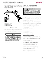
Страница 26: ...mbly Packing Tube Cascade and Barrel Equipment Required Special Multi Purpose Wrench 79854 00 4mm 3mm and 2 5mm Allen Wrenches Screwdriver blade Jam Nut Removal Tool 79793 00 Dielectric Grease LSCH0009 00 Sealant Medium Strength 7969 10 Dowel 6mm 1 4 diameter Note Supplied with applicator APPLICATOR REPAIR Figure 15 kV Probe There is a 10 giga ohm resistor in the probe that lowers the output volta...

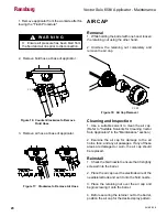
Страница 27: ...or Cleaning Vector Solo Applicators in the Maintenance section 2 Examine the air cap for damage to the air horns face and any air passages If any of these areas are damaged or worn the air cap should be replaced Reinstall 1 Check the fluid nozzle to ensure that it is tightly screwed into the barrel 2 Place the air cap over the electrode wire of the needle electrode and set it onto the fluid nozzle...

Страница 28: ...zzle with theopen endofthespecialmulti purposewrench Figure 20 Applicator Front End Components To keep the needle electrode from unscrewing from the needle shaft the applicator s trigger should be actuated to pull the needle electrode away from the fluid nozzle NOTE Cleaning and Inspection 1 Use a suitable solvent to clean the fluid nozzle Refer to Suitable Solvents for Cleaning Vector Solo Applic...

Страница 29: ...he thread of the barrel NEEDLE ELECTRODE Removal 1 Remove the air cap and fluid nozzle from the applicator assembly 2 Secure the needle shaft at the rear of the barrel with the Special Wrench 79854 00 and unscrew the needle electrode from the needle shaft Cleaning and Inspection 1 Use a suitable solvent to clean the needle electrode 2 Examine the needle electrode for damage or wear Pay special att...

Страница 30: ...r that will read 15 megohms accurately connectthefirstmeterleadtothemetal needle shaft and the second lead to the needle electrode wire The needle electrode resistance should be 14 5 to 19 megohms nominal 15 meg ohms at 9 volts or 12 to 17 megohms at 1000 volts Needle electrodes outside these ranges must be replaced Figure 23 Testing Resistive Electrode BARREL REMOVAL 1 Remove air cap and fluid no...

Страница 31: ... Remove the two 2 jam nuts using the 79793 00 Removal Tool while holding the needle shaft with the 79854 00 Special Wrench Figure 27 Jam Nut Removal 6 Remove three 3 5mm screws using a 4mm Allen wrench Remove the hook Figure 28 Barrel Screw Removal 7 Pull the barrel straight away from the handle Figure 29 Barrel Removal Ransburg ...

Страница 32: ...stallation Reinstalling Barrel 1 Replace the hook Install the barrel against the handle and hand tighten two 2 long 5mm screws in an alternating sequence with the 4mm Allen wrench Tighten the hook screw with the same 4mm wrench 2 Install the first jam nut Tighten to stop by hand while holding the needle shaft Figure 33 First Jam Nut Replacement Figure 32 Installing Barrel to Handle 2 Slide the cas...

Страница 33: ...ent 4 Install the fluid adjustment assembly along with the air and fluid return springs Figure 36 Fluid Line Trigger Installation Figure 35 Spring and Fluid Adjust Valve Replacement 5 Install trigger and fluid line and torque fluid tube fittings 40 45 lbs in 6 Reconnect the rear cover and install with two 2 4mm screws 1 Fluid Return Spring 2 Fluid Adjustment Valve 3 Air Valve Return Spring Ransbur...

Страница 34: ...dentification section for breakdown Needle Shaft Rebuild 1 Prior to installing the needle shaft coat the exteriorsurfacesgenerouslywithdielectricgrease 2 Screw the needle electrode onto the front of the needle shaft and hand tighten 3 Fill the inner diameter of the packing tube with dielectric grease 4 Insert the needle shaft rear section first into the packing tube Rotate the needle shaft while m...

Страница 35: ... 1 Remove the fluid line Figure 44 Fluid Line Removal Be generous with the dielectric grease when applying it to the packing tube and needle shaft This helps to remove air voids from this chamber DO NOT apply so much grease that it creates an air lock during assembly of the applicator NOTE 2 Remove three 3 bolts using a 3mm Allen wrench 5 With your finger wipe the excess grease from both ends of t...

Страница 36: ...ut the air valve cartridge Figure 49 Air Valve Cartridge Removal Figure 47 Air Valve Removal Handle Disassembly 1 Remove barrel 2 Remove power module 3 Push air valve out Figure 46 Power Module Removal The power modules are not serviceable NOTE 1 Push Out From Here 1 6mm 1 4 Dowel 3 Pull the module straight off the handle Ransburg ...

Страница 37: ... valve cartridge seal Figure 51 Air Valve Seal Replacement If you remove the air valve seal it is highly recommended that it is replaced NOTE Handle Rebuild 1 Install the front air valve seal using the Special Tool 1 Rear Seal 2 Air Valve Cartridge Seal 3 Front Air Valve Seal 1 79793 00 Jam Nut Tool 2 Front Air Valve Seal Concave Side to Tool Only remove the front air valve seal item 3 if there is...

Страница 38: ...er module from handle 2 Removetwo 2 screwsusinga2 5mmAllenwrench 4 Install the rear seal 5 Install air valve Figure 54 Rear Cartridge Seal Replacement Figure 55 Air Valve Replacement Figure 56 Power Module Removal Figure 53 Air Valve Cartridge Alignment 3 Installtheairvalvecartridge Alignthecartridge with tab at 12 o clock posiition ...

Страница 39: ... lbs in 3 Remove the 1 4 module from the 3 4 module Pull the fluid fitting out Figure 58 Fluid Fitting Removal 2 Install the fluid fitting Figure 60 Fluid Fitting Replacement Figure 59 Ground Clip Replacement Fitting Replacement 1 Ensure the ground clip is properly installed Tabs must be touching the air and fluid fitting Figure 62 Power Module Assembly The ground clip must be properly installed s...

Страница 40: ... follows see Figures 63 and 64 1 Connect the left hand fitting of the 79727 Air HosetothemaleinletoftheTestandMaintenance Kit 2 Connect the 6 air hose assembly between the brass tee fitting and the gun air inlet 3 Connect the other end of the air hose to the regulated air supply 4 Turn on main air Trigger the applicator with kV switchonhigh downposition Readthepressure atthe100psipressuregauge Thi...

Страница 41: ...ect Tubing to the Air Fitting 6 TP 1 TP 2 Figure 68 Connect the PC Board to a Digital Multi Meter and True Earth Ground 5 Connect a wire from test point 2 on the PC board in the power module to a true earth ground 6 Connect a digital multi meter to test points 1 and 2 TP 1 Test Point 1 TP 2 Test Point 2 Ground True Earth The procedure to test the 79835 Power Module Assembly is as follows 1 Remove ...

Страница 42: ...ssuewitheither the cascade or the wire connections leading to it Air hose maintenance Air Hose Ground Wire End 1 Cuttheendoftheairhosesothat endissquare 2 Slide the sleeve and compression ring onto the air hose end Figure 70 Sleeve and Compression Ring 3 Push the stem of the fitting all the way into the into the air hose 4 Slide the compression ring and the sleeve into the fitting body and tighten...

Страница 43: ... be checked Using a Meg Ohm meter at 1000V measure the resistance from the lug of the ground wire to the body of the QD 79868 or the swivel nut 79930 The reading must be less than 5 Mega Ohms resistance end to end Figure 74 Tightening 79930 Fitting 4 With the 79868 DQ fitting hold the hose in one handandpress againstafirmsurfacewhileturning the body wrench flat clockwise Tighten till cap is approx...

Страница 44: ...t the fluid line at the applicator Replace or clean Replace or clean Reassemble tightened to stop Thin the material to a viscosity that is sprayable a Restrictor left out of barrel b The three 3 5mm barrel to handle screws are not properly tightened Ensure atomization air passages are clear of all foreign particles Ensure fluid nozzle is properly tightened On Off lever in wrong position Low pressu...

Страница 45: ...Vector Solo 65kV Applicator Parts Identification 41 AH 08 02 6 PARTS IDENTIFICATION Figure 77 Vector Solo 65kV Applicator Parts Breakdown Ransburg ...

Страница 46: ...1 79701 00 Hook Molded 1 22 79799 02 SHCS M4 X 30mm 1 23 Table A A Assembly Air Hose Solo 10 20 and 30m Lengths 1 24 79833 02 Assembly Handle Vector Solo 1 Includes Items 33 34 35 36 37 and 38 24A 79833 03 Assembly Handle Only 1 25 79835 00 Assembly Power Module 1 Includes Items 39 40 41 42 and 43 26 79768 00 Nut Fluid Jam Spring Guide 1 27 78636 00 Spring 1 28 79789 00 Assembly Rear Fluid Adjustm...

Страница 47: ... Fluid Nozzle 45 2 Trans Tech 122V Air Cap 1 8mm Fluid Nozzle 245 3 Round Spray 4 Standard Spray 65kV Air Cap 1 2mm Fluid Nozzle 48 0 No Fluid Hose 1 Fluid Hose 10m 33 ft 2 Fluid Hose 15m 49 ft 3 Fluid Hose 20m 60 ft 4 Fluid Hose 30m 99 ft 2 Two Finger Trigger 44 79861 00 Hose Exhaust 1 45 79793 00 Jam Nut Removal Seal Install Tool 1 46 79854 00 Wrench Vector Solo 1 Packing Adjust Barrel Removal N...

Страница 48: ...7 21 79869 00 79727 31 79869 00 A Air Hose Stem Standard Air Hose Standard Air Hose Standard Air Hose Standard Air Hose Air Hose W Quick Disconnect QD Stem Air Hose W Quick Disconnect QD Stem Air Hose W Quick Disconnect QD Stem Air Hose W Quick Disconnect QD Stem Description TABLE A AIR HOSE LENGTH AND AIR HOSE TYPE 10m 33 ft 15m 49 ft 20m 66 ft 30m 99 ft 1 2 3 4 5 6 7 8 79374 65 80101 44 79809 00...

Страница 49: ...629 00 Retainer Needle Seal Rear 1 8 79001 06 O Ring Solvent Proof 1 9 10051 05 Cup Seal Spring Loaded 1 10 78630 00 Spacer Seal 1 11 17390 04 Washer Spring Belville 6 12 78631 00 Nut Packing 1 Item 79911 00 NEEDLE SHAFT PARTS LIST Figure 78 Part Description Qty Figure 78 79911 00 Needle Shaft With 2k Adjustable Packings 0 No Fluid Hose 1 Fluid Hose 10m 33 ft 79548 10 2 Fluid Hose 15m 49 ft 79548 ...

Страница 50: ... Needle Seal Rear 1 6 79001 06 O Ring Solvent Proof 1 7 10051 05 Cup Seal Spring Loaded 1 8 78630 00 Spacer Seal 1 9 78631 00 Nut Packing 1 Item 79911 01 NEEDLE SHAFT NON ADJUSTABLE PACKINGS FOR 1K ONLY PARTS LIST Figure 79 Part Description Qty 1 79755 00 Fluid Inlet 1 2 79746 00 Grounding Clip 1 3 79814 00 SHCS 4mm X 20mm Lg 2 4 Ref 1 4 Power Module 5 Ref 3 4 Power Module Item POWER MODULE REPLAC...

Страница 51: ...m 1 3 7617 00 Ferrule 1 4 77031 XX Bulk Hose Fluid XX Item FLUID HOSE PARTS LIST OPTIONAL Figure 81 Part Description Qty Figure 81 Fluid Hose Optional ACCESSORIES Figure 82 Air Hose Assembly Parts 1 79869 00 Stem Quick Disconnect Air Fitting 1 2 20 LH 1 2 79868 00 Assembly Quick Disconnect Fitting 1 3 79930 00 Hose Fitting Assembly 1 2 20 LH 1 4 79938 00 Assembly Ground Fitting 1 Item AIR HOSE ASS...

Страница 52: ...ssembly 10 meter 33 foot QD Air Hose Assembly 10 meter 33 foot QD Air Hose Assembly with Stem 10 meter 33 foot Standard Air Hose Assembly 15 meter 49 foot QD Air Hose Assembly 15 meter 49 foot QD Air Hose Assembly with Stem 15 meter 49 foot Standard Air Hose Assembly 20 meter 66 foot QD Air Hose Assembly 20 meter 66 foot QD Air Hose Assembly with Stem 20 meter 66 foot Standard Air Hose Assembly 30...

Страница 53: ...NCE KIT OPTIONAL Figure 84 Part Description Figure 84 Test and Maintenance Kit Optional Figure 85 Coiled Fluid Tube 79871 00 Coiled Fluid Tube 3 2mm 125 16 Coils 79871 01 Coiled Fluid Tube 3 2mm 125 12 Coils 79890 00 K5 Cover Coiled Fluid Tube Kit of 5 COILED FLUID TUBE OPTIONAL Figure 85 Part Description Ransburg ...

Страница 54: ...nstallation and Setup Kit is available for the Vector Solo This kit includes all equipment necesaryfortheinstallation setup andmaintenance of the Vector Solo applicator This kit includes Figure 87 Installation and Setup Kit 1 Cap Pressure Test Gauges 2 Test Air Caps 65V 98V 122V 3 100 ml Graduated Cylinder 4 Analog Voltmeter 5 Stop Watch 6 Test and Maintenance Kit 7 Wet Film Gauge 79651 00 INSTALL...

Страница 55: ...NS TECH ATOMIZATION PARTS LIST Part Description Qty 79374 65 Standard Air Spray Air Cap 79374 122 Trans Tech Air Spray Air Cap 80101 XX Standard Air Spray Fluid Nozzle 80122 XXX Trans Tech Air Spray Fluid Nozzle 79809 00 Standard Air Spray Restrictor 74963 06 Trans Tech Air Spray Restrictor PARTS COMPARISON Standard Air Spray Nozzles have a number between 44 and 148 Trans Tech Air Spray Nozzles ha...

Страница 56: ...4 00 Screw Trigger Retention 2 79768 00 Nut Fluid Jam Front 1 79744 00 Spring Air Valve Return 1 79835 00 Assembly Power Module Includes Items 39 40 41 42 and 43 1 79768 00 Nut Fluid Jam Spring Guide 1 78636 00 Spring 1 79781 00 Seal Adjustment Bushing 1 79837 00 Gasket Handle to Power Module 1 79809 00 Pressure Reducer Atomizing Air Vector Solo Yellow 1 79911 00 Kit Shaft Assembly 2 Piece Needle ...

Страница 57: ...53 AH 08 02 6 Vector Solo 65kV Applicator Parts Identification NOTES Ransburg ...

Страница 58: ... 1 yearfromdateofpurchase wrapping theAPPLICATOR ASSOCIATEDVALVESAND TUBING AND SUPPORTING HARDWARE IN PLASTIC SHRINK WRAP OR ANY OTHER NON APPROVEDCOVERING WILLVOIDTHIS WARRANTY RANSBURG S ONLY OBLIGATION UNDER THIS WARRANTY IS TO REPLACE PARTS THAT HAVE FAILED BECAUSE OF FAULTY WORKMANSHIPORMATERIALS THEREARE NOIMPLIEDWARRANTIESNORWARRANTIES OF EITHER MERCHANTABILITY OR FITNESS FOR A PARTICULAR ...

Страница 59: ...e Manual AH 08 02 5 Vector Solo 65kV Applicator to make the following changes 1 Updated manual due to nozzle thread change addition of Air Stream one way Valves and clarification of special conditions for safe use Vector Solo 65kV Applicator Warranty Policies Ransburg ...

Страница 60: ...g Spare Parts Manufacturing 1910 North Wayne Street Angola Indiana 46703 9100 Telephone 260 665 8800 Fax 260 665 8516 Technical Service Assistance 320 Philips Ave Toledo Ohio 43612 1493 Telephone toll free 800 233 3366 Fax 419 470 2233 2013 Ransburg All rights reserved Models and specifications subject to change without notice Ransburg ...

Отзывы: