background image

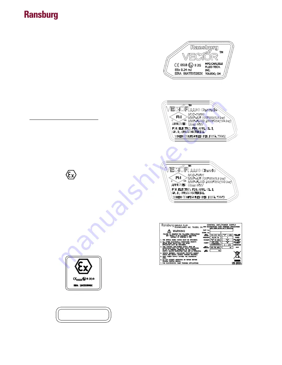
Label 79515

Vector AA90 79580 and 79581 

ATEX Product Marking Definitions

Ex Certificate Number: Sira 06ATEX5282X 

Sira = Notified Body performing EC-type examination

06 = Year of certification

ATEX = Reference to ATEX Directive

5 = Protection Concept Code (code 5 is titled 

Encapsulation)

282 = Document serial number

X = Special conditions for safe use apply

Special conditions for safe use: 

The Vector 79581 AA90 Classic Series Applicator 

shall only be used with associated 80130 Series 

Power Supply.

The Vector 79580 AA90 Cascade Series Applicator 

shall only be used with associated 80131 Series 

Control Unit.

Product Marking

II 2 G

Ex = Specific marking of explosive protection

II = Equipment Group hazardous area charac-teristics

2 = Equipment Category

G = Type of explosive atmosphere (gases, vapors, 

or mists)

EEx 0.24mJ

  The Vector 79581 AA90 Classic 

Series and 79580 Cascade Series Applicators are 

suitable for use in automatic spraying installations 

complying with EN 50176 as they are a Type A 

class with a discharge energy limit of 0.24mJ.

Label 79612-01

Label 79612-02

FM Configuration

These applicators are FM approved when config-

ured to drawing 79952, 79953 shown on pages 

9 thru 12.

E N   5 0   0 5 0   COM P L I A N T

Label 80082

Label 80081

Label 80108

Vector AA90 Applicators - Atex

6

AH-07-01.10

Содержание Vector AA90 Cascade

Страница 1: ...9 MAY 2015 Ransburg IMPORTANT Before using this equipment carefullyreadSAFETYPRECAUTIONS starting on page 1 and all instructions in this manual Keep this Service Manual for future reference Service Ma...

Страница 2: ...E This manual has been changed from revision AH 07 01 9 to revision AH 07 01 10 Reasons for this change are noted under Manual Change Summary on page 57 of this manual Vector AA90 Applicators AH 07 01...

Страница 3: ...ES 14 CLASSIC SPECIFICATIONS SOLVENTBORNE CLASSIC 15 80130 41X 9060 POWER SUPPLY ELECTRICAL SPECIFICATIONS 15 AA90 CLASSIC SOLVENTBORNE ELECTROSTATIC SPRAY APPLICATOR FEATURES AIR ASSIST 16 80130 14X...

Страница 4: ...SSEMBLY CLEANING PROCEDURE 35 42 TROUBLESHOOTING GUIDE 43 45 MAINTENANCE 33 45 PARTS IDENTIFICATION 46 56 79580 VECTOR AA90 APPLICATOR MODEL IDENTIFICATION 46 79581 VECTOR AA90 APPLICATOR MODEL IDENTI...

Страница 5: ...priate Ransburg equipment manuals to reconcile such differences Carefulstudyandcontinueduseofthismanualwill provide a better understanding of the equipment and process resulting in more efficient oper...

Страница 6: ...ure Otherwise the cleaning process must be carried out in an area with forced air ventilation It is the end users responsibility to insure this condition is met Spray booth ventilation must be kept at...

Страница 7: ...components The chemical reaction caused by these sol vents reacting with aluminum can become violent and lead to an equipment explosion Sprayapplicatorsrequirethataluminuminletfittings be replaced wi...

Страница 8: ...egohm C Every metal and conductive object in the spray area This includes the booth parts hangers fire extinguishers conductive flooring etc Grounded conductive flooring must be provided in the spray...

Страница 9: ...personnel in accordance with the manufacturer s documentation 8 The certification of this equipment relies upon the following materials used in its construction If the equipment is likely to come int...

Страница 10: ...hall only be used with associated 80131 Series Control Unit Product Marking II 2 G Ex Specific marking of explosive protection II EquipmentGrouphazardousareacharac teristics 2 Equipment Category G Typ...

Страница 11: ...CONFIGURATION DWG 79952 REV A E DESIGNATIONS B DESIGNATIONS C DESIGNATIONS A DESIGNATIONS D DESIGNATIONS Vector AA90 Applicators Atex 7 AH 07 01 10...

Страница 12: ...91 1013 1018 TIP 79691 1018 1021 TIP 79691 1021 1311 TIP 79691 1311 1313 TIP 79691 1313 1315 TIP 79691 1315 1318 TIP 79691 1318 1511 TIP 79691 1511 1513 TIP 79691 1513 1515 TIP 79691 1515 1518 TIP 796...

Страница 13: ...CONFIGURATION DWG 79953 REV A E DESIGNATIONS B DESIGNATIONS C DESIGNATIONS A DESIGNATIONS D DESIGNATIONS Vector AA90 Applicators Atex 9 AH 07 01 10...

Страница 14: ...IGNATIONS FLUID HOSE LENGTH 0 FOR NO FLUID HOSE 1 FOR 11m 36FT FLUID HOSE PART NUMBER 7994 36 2 FOR 15m 50FT FLUID HOSE PART NUMBER 7994 50 3 FOR 25m 75FT FLUID HOSE PART NUMBER 7994 75 4 FOR 30m 100F...

Страница 15: ...f the coating is deposited on the target One of the many features of the Vector AA90 applicator system is that the electrical energy which is available from the resistive charging electrode is limited...

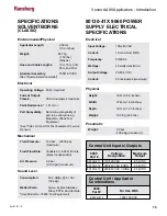
Страница 16: ...Variable to 1 500 cc minute spray tip dependent Air Pressure 6 9 bar 0 100 psi maximum Applicator Length 25 9cm 10 2 inches Weight 760g 1 67 lbs Cascade Hose and Cable Lengths 10m 15m 20m 25m and 30m...

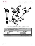
Страница 17: ...Replaceable Hook Fan Air Adjust 2 Finger Trigger AA90 CASCADE SOLVENTBORNE ELECTROSTATIC SPRAY APPLICATOR FEATURES AIR ASSIST 6 7 8 9 10 No Description Trigger Lock Assembly Fluid Hose Connection Air...

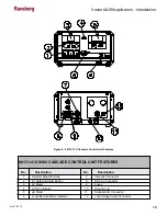
Страница 18: ...t Adjust Button kV Meter HV On Indicator A Meter Local Remote Mode Indicator 80131 41X 9060 CASCADE CONTROL UNIT FEATURES 7 8 9 10 11 12 No Description Interlock Connector AC Line Connector Fuses Grou...

Страница 19: ...30 psig Wetted Parts Nylon Acetal Stainless Steel PTFE and Carbide Use Model No 76652 Test Equipment Environmental Physical Electrical Mechanical Sound Level 80130 41X 9060 POWER SUPPLY ELECTRICAL SPE...

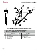
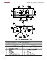
Страница 20: ...lectrode Barrel HP Replaceable Hook Fan Air Adjust 2 Finger Trigger AA90 CLASSIC SOLVENTBORNE ELECTROSTATIC SPRAY APPLICATOR FEATURES AIR ASSIST 6 7 8 9 No Description Trigger Lock Assembly Fluid Hose...

Страница 21: ...oint Button 80130 41X 9060 POWER SUPPLY FEATURES 9 10 11 12 13 14 15 16 Description kV Setpoint Adjust Buttons Air Flow Switch Connections Low Flow High Voltage Cable Connector Standard I O Connector...

Страница 22: ...the applicator system Ensure thatalltargetobjectshavearesistanceto ground of one megohm or LESS This information is intended ONLY to indicate general installation guidelines of this product and its wo...

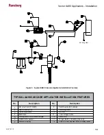
Страница 23: ...gulator W Pressure Gauge Air Water Separator Main Air Supply TYPICAL AA90 CASCADE APPLICATOR INSTALLATION FEATURES 8 9 10 11 12 13 14 No Description Fluid Supply Grounded Fluid Regulator Air Line Low...

Страница 24: ...int line to the applicator electrode must be prevented by grounding the paint line at the applicator handle Verify that the applicator handle is ac tually grounded before operating it This is done wit...

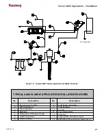
Страница 25: ...gulator W Pressure Gauge Air Water Separator Main Air Supply TYPICAL AA90 CLASSIC APPLICATOR INSTALLATION FEATURES 8 9 10 11 12 13 14 No Description Fluid Supply Grounded Fluid Regulator Air Line Low...

Страница 26: ...close to areas of high temperature 129 F The operator should have free movement of the applicator andallbendradiiofthecableshouldnot be less than 6 inches 15cm Connect the high voltage cable to the p...

Страница 27: ...e coating material by the atomization and fan air NOTE Use only hose rated at 6 9 bar 100 psig working pressure or above W A R N I N G Use only high pressure hose rated at 193 bar 2800 psig working pr...

Страница 28: ...or substantial property damage Consult your fluidsuppliertodeterminethechemicalcontent of your solvents See HHC Explosion Hazard Danger Sign and Halogenated Hydrocarbon Safety Bulletin Never flush th...

Страница 29: ...a specific article with maximum effi ciency is not an exact science Testing is usually necessary and wide experience with many types of coating applications helps Your Ransburg representative uses suc...

Страница 30: ...511 79691 1513 79691 1515 79691 1518 79691 1521 79691 1715 5 in 127 8 in 203 10 in 254 13 in 330 15 in 381 AA90 Fluid Nozzle Part Pattern Width at 10 in mm Nozzle Orifice Size in Inches mm 009 23 011...

Страница 31: ...eds to be turned off for spraying into recessed areas When the kV is disabled in this manner the kV meter will DO NOT turn the applicator off using the applicator button in place of interlocking with...

Страница 32: ...at may be reset the Figure 33 Display In High Voltage On Time Figure 31 A Bar Graph Meter Display otherthatispermanentlyretainedinmemory The number of hours the unit s high voltage has been on may be...

Страница 33: ...hese setpoints can be individually adjusted between 20 and full kV using the and buttons on the front panel of the power supply When the or buttons are held in longer than 1 second the kV display will...

Страница 34: ...ased transfer efficiency Figure 39 Local Remote Mode Button If unit is in remote mode with no external signal the unit will not function The unit must be in local mode C A U T I O N Local Remote Mode...

Страница 35: ...the plug assembly with a wrench turning counter clockwise and unscrew the nut by hand Remove the low voltage cable by pulling it from the plug assembly Classic Applicator Pull the clip on the high vol...

Страница 36: ...sembly Classic Air Valve Rod Assembly 79310 00 Apply sealant 7969 10 to the external threads of the following parts when assembling Air Valve Retaining Nut EQUIPMENT REQUIRED Special Multi Purpose App...

Страница 37: ...plicator and low voltage or high voltage cable with a solvent dampened cloth NEVER soak or submerge the electrical components of the applicator i e cascade barrel assembly assembly or cable assem bly...

Страница 38: ...shed before voltage is applied W A R N I N G 4 Line up the hole in the test probe and the electrode Slide the test probe straight over the electrode wire of the applicator 5 Holding the metal portion...

Страница 39: ...hed soon enough the internal passages may be come clogged This can lead to excessive downtime for repair C A U T I O N Before cleaning the nozzle assembly turn the control unit or power supply OFF and...

Страница 40: ...d triggering the applicator will not release the pressure Cover the end of the applicator with a heavy rag and loosen the nozzle nut slowly into a grounded catch container Any broken or damaged compon...

Страница 41: ...le 3 Push the spray tip and holder out of the air cap by pressing with a finger or soft object on the car bide or tapered portion of spray tip The carbide spray tip contains a removable nozzle seal wi...

Страница 42: ...mbly Needle Shaft Packing Replacement 1 Removespringsprayretainerandlocknutfrom shaft Pull all rear seal parts off shaft Replace components as required Figure 45a Needle Shaft Packing Replacement 2 Us...

Страница 43: ...Install jam nut all the way on the shaft Install the carbide ball all the way down using two 74133 tools Tighten the jam nut against the carbide ball 3 Install rest of parts in reverse order Ensure a...

Страница 44: ...nceontheshaft may be felt when the shaft is pushed in and out Figure 48c Rebuilding Barrel Install Barrel on Handle 1 Adjust spring retainer and locking nut to dimen sion shown Tighten against each ot...

Страница 45: ...move air valve and air valve seal Handle Disassembly 1 Remove the barrel 2 Remove the fluid tube from the bracket Figure 49b Install Barrel on Handle Figure 50a Handle Disassembly Figure 50b Handle Di...

Страница 46: ...move resistor tube as sembly Figure 50g Handle Disassembly Apply LSCH0009 00 dielectric grease to resistor tube prior to reassembly Figure 50h Handle Disassembly Handle Reassembly 1 Reversedisassembly...

Страница 47: ...Clogged nozzle 2 Clogged hose or filters 3 No pressure at paint pump 1 Clean out 2 Increase pump air pressure 3 Try nozzle with narrower fan or smaller orifice 4 Try nozzle with narrower fan or smalle...

Страница 48: ...worn 1 Loose packing nut 1 Evaporation rate too fast 2 Poor atomization 3 Viscosity too high 1 Low solids paint 2 Low viscosity 3 Excessive delivery 1 Remove restriction 2 Secure larger pump or reduc...

Страница 49: ...iggered 11 Is the applicator switch on 12 Is the paint too conductive 13 Faulty flow switch 1 Failed fluid hose 2 Isolation stand or charged equipment too close to ground 1 Check and secure at the app...

Страница 50: ...h Meters 0 1 2 3 4 5 Dash No 2 Finger Trigger 79325 12 Description 2 Dash No TABLE B Trigger Type B 0811 Tip 0813 Tip 1011 Tip 1015 Tip 79691 0811 79691 0813 79691 1011 79691 1015 Description 0 1 2 3...

Страница 51: ...3 4 5 Dash No 2 Finger Trigger 79325 12 Description 2 Dash No TABLE G Trigger Type G 0811 Tip 0813 Tip 1011 Tip 1015 Tip 79691 0811 79691 0813 79691 1011 79691 1015 Description 0 1 2 3 Dash No TABLE...

Страница 52: ...1 Vector AA90 Cascade Exploded View 41 42 44 2 18 19 20 21 22 26 27 28 29 30 31 35 36 33 37 38 1 9 4 3 5 39 40 7 6 8 10 11 13 14 15 16 17 2 12 32 23 Vector AA90 Applicators Parts Identification 48 AH...

Страница 53: ...port Offset 1 19 74189 00 Fitting Air Inlet REM 1 20 79001 08 O Ring Solvent Proof 1 21 Table B B Trigger Molded 1 22 79454 00 Screw Trigger Retention 2 23 79638 00 Trigger Lock Assembly 1 24 25 26 83...

Страница 54: ...AA90 Classic Exploded View 45 47 2 9 38 4 14 26 39 44 43 41 42 40 37 36 15 10 25 30 21 16 3 5 7 8 17 18 39 8 3 23 27 24 1 22 19 35 33 34 32 31 28 29 20 6 11 Vector AA90 Applicators Parts Identificatio...

Страница 55: ...Air Valve 1 22 79310 00 Rod Assembly Dual Stage Air Valve 1 23 79471 11 Assembly Rear Housing AA90 Classic 1 24 79453 00 Cap Retaining Air Valve 1 25 8301 08C SHCS 1 26 17130 00 Spring Return 1 27 790...

Страница 56: ...over 1 79529 00 K5 Disposable Applicator Cover Lots of 5 7 74187 02 Air Hose Assembly 2m Whip 6 5 ft 1 8 77105 00 Adapter 3 8 AN Male to 1 4 NPSM M 1 9 79338 01 1 Meter Low Voltage Cable 79580 Vector...

Страница 57: ...up 1 3 72378 01 Packing Tube 1 4 73347 00 Container Rear Seal 1 5 74330 00 Seal High Pressure 1 6 73348 00 Retainer Real Seal 1 7 72209 05 O Ring Metric 1 8 73354 00 Nut Packing 1 9 79572 00 Assembly...

Страница 58: ...1 Contains 2 and 3 2 79001 16 O Ring Solvent Proof 1 3 79001 07 O Ring 1 Item Part Description Qty FAN AIR VALVE PARTS LIST Figure 56 Figure 56 Fan Air Valve Components 3 2 1 Vector AA90 Applicators P...

Страница 59: ...High Pressure Seal 1 1 75326 00 Air Cap Retaining Ring 1 1 77096 00 Fluid Tube Assembly 1 1 7720 01 Paint Filter 100 Mesh 1 1 7720 02 Paint Filter 60 Mesh 1 1 78824 00 Spring 1 1 79566 10 Fan Air Valv...

Страница 60: ...CIATEDVALVESAND TUBING AND SUPPORTING HARDWARE IN PLASTIC SHRINK WRAP OR ANY OTHER NON APPROVEDCOVERING WILLVOIDTHIS WARRANTY RANSBURG S ONLY OBLIGATION UNDER THIS WARRANTY IS TO REPLACE PARTS THAT HA...

Страница 61: ...use information in ATEX section with appropriate gun model numbers and their corresponding control units and power supplies 2 Added additional explanations of specific cascade or classic unit fault c...

Страница 62: ...re Parts Manufacturing 1910 North Wayne Street Angola Indiana 46703 9100 Telephone 260 665 8800 Fax 260 665 8516 Technical Service Assistance 320 Philips Ave Toledo Ohio 43612 1493 Telephone toll free...

Отзывы: