

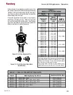


The green and yellow regions of the bar graph
meter indicate output current is in the optimum
range for maximum transfer efficiency. The red
region of the bar graph indicates high output current
causing decreased transfer efficiency.
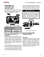
The display at the rear of the applicator also
doubles as a microamp bar graph meter when
high voltage is on (see Figure 30). Its' function is
similar to that of the control unit bar graph display.
Figure 32: View of Applicator LED Display
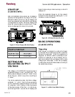
Measuring "High Voltage On" Time
The 9060 Power Supply records the amount of
time the high voltage is triggered on up to 99,999
hours. These units are displayed in the kV and µA
displays of the unit. There are two registers that
retain this information, one that may be reset, the
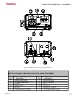
Figure 33: Display In "High Voltage On" Time
Figure 31: µA Bar Graph Meter Display
other that is permanently retained in memory. The
number of hours the unit's high voltage has been
on may be displayed by depressing at the same
time the preset 1 and reset buttons. The display
will show hours of use for 3 seconds. This is the
re-settable register.
To reset this register, press the reset button while
the hours are displayed. Pressing the preset 2
and reset buttons at the same time will show the
number of hours on the non-re-settable register.
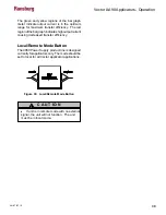
Local/Remote
The Vector product line is designed currently for
applicators only. The local/remote high voltage
control switch should be set to local for all Vector
applicator applications.
Figure 34: High Voltage Control Switch
The unit will not function if it is in remote
mode without external inputs.
C A U T I O N
!
Vector AA90 Applicators - Operation
28
AH-07-01.10


