Rangevision Standard Plus Скачать руководство пользователя страница 22


22 


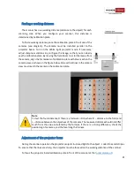
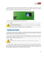
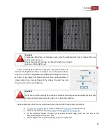
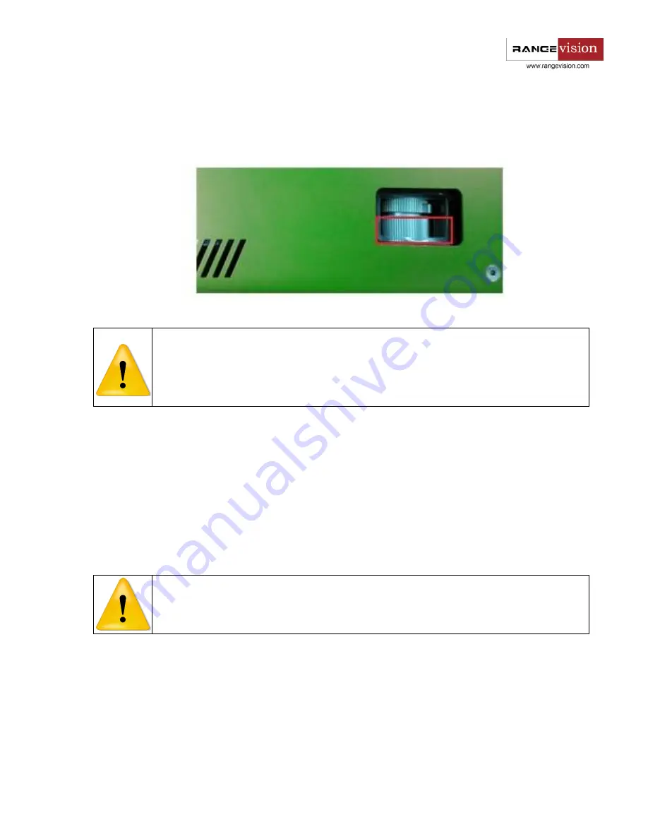
By  switching  the  mode  "Lines  and  Stripes",  adjust  the  focus  of  the  projector,  so  that  the  lines  on  the 

calibration plate were as sharp as possible. Using the zoom ring set the minimum possible area of projector 
light in such a way that the whole field is lit with a small margin to the height. 


After changing the illumination area check the projector focus. 


Note


Minimum light area of Acer projectors (zoom ring in the last position) allows you to configure 
focus for any calibration plate.  
For other projectors, depending on the scan area, using the zoom ring you can select that 
area of light, in which all the plate will be lit, or use special lenses. 

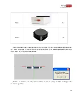
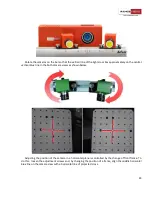
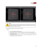
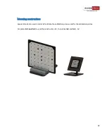
Bringing the cameras together 

For the work of the scanner it is necessary to point both cameras to the same position on the specified 

working distance. Install the calibration plate in front of the scanner on the found working distance D (if you 
changed its position after the projector focusing procedure). 

Turn on the 

Cross

 light mode and aim the scanner to the calibration plate. It is not necessary to combine 

cross with marks on the plate at this stage, the focused projector should be projecting a cross on any surface, 
located at the working distance D from the scanner. 
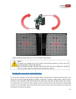
 

Note


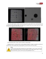
If the images from the cameras are very dark, tune the iris and the focus on the cameras. 

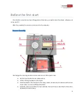
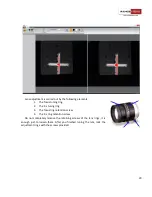
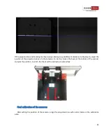
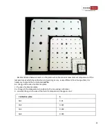
Install the cameras in position, corresponding to selected scan area. It is necessary to align black risks on 

the front of the scanner, labelled 1,2,3,4 , with inner edge of the camera mounting plate. To do this, loosen 
the mounting bolts and move the camera to the desired position. Position 4 is similar for both cameras. On 
the image below the cameras are set in the position for scanning area №2. 

Содержание Standard Plus

Страница 1: ...1 RangeVision ScanCenter 2016 1...

Страница 2: ...arameters 13 Connecting the turntable 14 Scanner setup 17 First launch of ScanCenter 18 Inital setup of cameras and lenses 19 Finding a working distance 21 Adjustment of the projector focus 20 Bringin...

Страница 3: ...o object 39 Setting exposure of the cameras 40 Starting and stopping the scanning process 40 Viewing the model 40 Unwanted noise on the 3D model 41 Scanning without markers 42 Scanning with markers 42...

Страница 4: ...ublications System requirements Operating system Windows 7 8 10 64bit Processor Intel Core i5 2 0 GHz and better RAM Not less than 4 GB Graphics Card Graphics card with HDMI output Other 3 USB ports W...

Страница 5: ...R ngeVisi n is not a metrological tool for measuring Scanning zone number 1 2 3 4 0 Scanning Area WxHxD mm 460 345 345 300 225 225 133 100 100 66 50 50 850 530 530 3D point accuracy 0 085 mm 0 05 mm 0...

Страница 6: ...ark objects Package contents R ngeVisi n 3D scanner is supplied in a plastic box with lodgement optionally can be supplied in a protected road hard case Camera tripod is placed in a separate bag The s...

Страница 7: ...2 Machine vision camera 2 3 Tripod 1 4 Calibration plate 1 4 5 Kit of interchangeable optics 1 5 6 Stand for the calibration plate 1 2 7 USB disk with the software 1 8 The electronic key 1 9 Matting s...

Страница 8: ...Carefully get the scanning module and all accessories out of the plastic case Set the tripod on the flat and stable surface Fit the scanning module 1 on the tripod Install module 2 on the front part...

Страница 9: ...electronic key 8 into a free USB port Connect the rotary table 14 if equipped to your computer using the USB cable connect the power cord 3m cable Installing software and drivers Get the R ngeVisi n...

Страница 10: ...or After connecting the projector it should be displayed in the system If the computer has several video outputs define the one to be used Note If the second monitor projector is not defined by the sy...

Страница 11: ...settings of your projector are reset which can have an adverse impact on the scanner operation If this happens you need to adjust your projector using the control buttons on its body You must set the...

Страница 12: ...ong with this the projector must be set up as mentioned above When using light filters there is no need to change user settings of projector color temperature for previous versions UAC setting For the...

Страница 13: ...le most likely it is used by some third party application for example Skype Turn off the software which uses cameras and check camera availability in IDS Go to the menu item Additional settings and di...

Страница 14: ...e name of connected device in Device Manager may be different for example Silcon Labs Arduino Uno Rangevision Table and so on Go to the Device Manager in the computer properties and look the number of...

Страница 15: ...15 Model Type Additional power supply Default till 01 2016 Yes...

Страница 16: ...nnected and all the settings are correct you will see the graphic mode of the table platform in the 3D model preview area In case of an error you will see the corresponding message Check the connectio...

Страница 17: ...direction change the settings of the parameter Change direction in the configuration settings In contrastto the other modes before scanning on the turn tableyou should firstevaluate its axis perform t...

Страница 18: ...tighten the lenses and light filters Place the calibration plate on the stand in front of the scanner Size of calibration plate is specified in the table on the back side of each plate Scanning zone T...

Страница 19: ...t also check whether such programs as ICQ Skype Sipp int or similar software use one of the cameras as a web camera Initial setup of cameras and lenses Caution Check that the right hand camera represe...

Страница 20: ...g ring 2 The iris tuning ring 3 The focus ring retention screw 4 The iris ring retention screw Do not completely remove the retaining screws of the lens rings it is enough just to loosen them After yo...

Страница 21: ...th blue mesh on the camera view as shown in the figure below Blue vertical lines in the camera view must match the marks on the calibration plate Note To test the found distance D there is a formula L...

Страница 22: ...e position on the specified working distance Install the calibration plate in front of the scanner on the found working distance D if you changed its position after the projector focusing procedure Tu...

Страница 23: ...line in the both camera views as shown below Adjusting the position of the camera in a horizontal plane is controlled by the change of front frame To do this loosen the adjustment screws and by changi...

Страница 24: ...rizontal plane For the correct operation of the scanner projector beam and optical axis of cameras must be lying in one plane This is done through regulating the position of cameras in relation to the...

Страница 25: ...tion of the projector relative to the cameras To do this loosen the body at the bottom of the scanner and pick the position in which the check will be carried out successfully Final calibration of the...

Страница 26: ...setting the exposure adjust sharpness of the lenses To do this turn on the Black light projector mode adjust the slider bar in the tool bar to a minimum value of electronic exposure value 1 open diap...

Страница 27: ...ith red mean overlit areas with too bright image Configure lenses iris so that the lines on the calibration plate are as bright as possible but without a significant amount of excessive light Image br...

Страница 28: ...ately 2 times greater than the brightness of the stripes Visually lines and stripes must be the same brightness Caution After the end of the setting up procedure carefully lock sharpness and diaphragm...

Страница 29: ...canner setup can be completed by following the prompts of setup wizard in RangeVision ScanCenter menu Run the setup wizard select scanning zone to which you need to set up the scanner and carefully re...

Страница 30: ...uspect that the camera moved due to unreliable mounting If you want to check the accuracy of performed calibration Before the work with the scanner recommended Calibration of rotary table is performed...

Страница 31: ...is very different from the specified it is necessary to amend the formula L L b Co L change of the size of calibration plate L the size of calibration plate o change in the temperature in relation to...

Страница 32: ...32 Mounting constructions Special stands are used in order to facilitate the calibration process and fix the calibration plates For plates 1 and 2 is used the construction S1 for plates 3 and 4 S2...

Страница 33: ...n the dropdown list choose the calibration plate in use Focal distance of the lenses is detected automatically when the field is selected from the list Caution Check that the size of the plate specifi...

Страница 34: ...itial accuracy value during calibration Working with the scanner don t forget to once in a while perform orientation it also serves as an accuracy indicator If the accuracy during orienting starts to...

Страница 35: ...ion command Mount the calibration plate at the central position in the distance D to the scanner the first calibration position Press the Capture button Next following the steps make two more shots Af...

Страница 36: ...D1 49 For example for scanning area 2 D1 49 236 mm Near end D1 49 2 118 mm Far end D1 49 2 118 mm Specify these values in the settings of plane clipping Adding new plates In the menu Service Full cali...

Страница 37: ...30x530 mm This scan area can be used only if there is already a scanning zone 1 To configure the scanning zone 0 Install lenses with focal length of 9 mm and Blue light filters on the cameras Perform...

Страница 38: ...objects that contain large contrast areas for example black lettering on white paper Geometrical distortion may appear in places with strong contrast Scanning principle and methods If you re shooting...

Страница 39: ...th where you want to save the project consider a large volume of scan data If you have created a project with markers the Markers dialogue box with a choice of colors appears it is described in more d...

Страница 40: ...ese parts or set the scanner for a larger scanning zone Setting exposure of the cameras After you place an object at the needed distance switch the projector to the Lines and Stripes lighting mode Adj...

Страница 41: ...view As long as computer resources allow it the model is displayed in the original quality without simplification When loading a project with a largeamount of data visualization of themodel can be sim...

Страница 42: ...ination Blue Light On lenses you should install special light filters which allow only the blue light projected by the scanner This allows to carry out scanning procedures in bright lighting condition...

Страница 43: ...and delete by pressing the Delete button Place an object or the scanner in a different position and scan the next fragment Thus scan the desired areas of the surface As you finished go to the S nMerge...

Страница 44: ...in different formats b segrid b txt from third party sources for example from photogrammetric system that allows you to scan large objects for example vehicles without significant loss in accuracy Wh...

Страница 45: ...a reference grid select the markers mode left picture below on the top toolbar If you are scanning the object itself with the grid or without it select the Model and markers mode right picture below o...

Страница 46: ...to the scanner so that during scanning the object is on the optimal distance from the scanner Configure exposure brightness of lines and stripes projector sharpness Go to Options set the scan area cl...

Страница 47: ...However if much more check the accuracy of installed lenses and that cameras location corresponds to the selected calibration plate by the scale The distance should be found from the plate The formul...

Страница 48: ...then the calculated diameter of a marker may not match the specified one and markers will not be considered as such Perform orientation or calibration In addition check the size of the markers specif...

Страница 49: ...s of rotary table is not evaluated The position of scanner or table changed after evaluation The scan object should be mounted in a fixed position on the area otherwise there may be slippage of the ob...

Отзывы: