


Manual-10
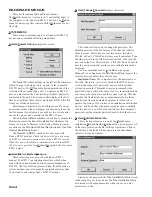
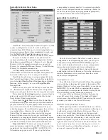
THE RANEWARE BUTTON BAR
This Button Bar appears at the top of every RW 232
product’s screen.
The 16 numbered buttons immediately recall the indicated
memory number from the connected RW 232 product. The
most recently recalled memory is indicated by the red
memory number to the left of the Store button. The red
memory number flashes when the current memory settings
have changed and no longer match the settings stored in the
flashing memory. If you wish to save the changed settings in
one of the 16 memories, click
Store
, and then click the
memory number in which you wish to store the settings. It’s
that easy! Go ahead and store different settings in different
memories. After storing a few, click any memory number to
instantly recall that memory. Store those settings you’ll use
most often in memories 1 through 8, since these can be
recalled via the rear panel Remote Switch contact closures
when the computer is removed.
Note: When you click the Store button, it appears in light-
gray until you select a memory in which to store the current
data. The red, most recently recalled memory number does
not change to the memory number you’ve stored to. As an
example, if you recall memory 3, make some changes, then
hit Store followed by memory 5 to store the changes in
Memory 5, the red memory number continues to indicate
memory 3 as the most recently recalled memory. Only if you
hit the memory 5 button a second time (after Storing) will
memory 5 actually be recalled. This means that storing to a
given memory does not automatically recall that memory.
To change any settings without affecting the audio, simply
select the
Local Edit
button, make the changes, then re-click
Local Edit
. You will be asked:
Accept the Changes?
Answering
Yes
sends those settings to the RPM. While
Local
Edit
is selected, clicking on any of the memory buttons
displays that memory’s settings without recalling them.
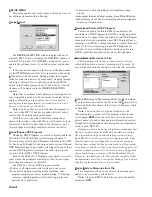
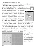
The
Device
button brings up a selection menu of up to 15
RW 232 units connected to the computer from the most recent
Poll. Simply select the device you wish to control.
cate with the selected unit since software launch. This number
should always be zero but could increase if the communica-
tions cabling becomes intermittent or open.
Note: Be sure you have the above Device Status informa-
tion as well as the version number of RaneWare you are using
(found under
Help|About...
) when calling the factory for
technical support.
HELP MENU
The
Help
menu provides extensive On-Line Help. There
is a help Index and a help Contents (F1) interface for quick
access to the information you may seek.
Also, the infamous
About...
selection displays the beauti-
ful RaneWare splash screen where the current RaneWare
application software revision is available. The revision
number in
Help|About...
is very important if you ever need
RPM 26 or RaneWare technical support from Rane.
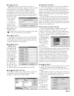
RPM 26 BASICS
The RPM 26 has 2 inputs, named Input A and Input B;
and 6 outputs, named Output 1 through Output 6. To display
these default names on the Device Edit screen, check the
Show Names
box at the bottom of the screen. These are the
default names of the RPM’s inputs and outputs. To change
these I/O default names or the device’s name to those that
apply to your install, select
Name Device
under the
Device
menu.
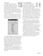
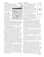
RAMPING
When the
Ramp Disable
check box at the bottom of the
Device Edit screen is unchecked, the RPM 26 slowly ramps
level and EQ setting changes. Ramping is provided as an
application level feature. For example, when changing from
one memory to another with program audio playing and
where EQ or level settings change, it is appropriate to ramp
between memories. During set up, however, it may be
distracting or deceiving to have settings ramp. Check the
Ramp Disable
box during set-up to avoid, for example,
running analysis sweeps too quickly after a change – i.e.,
before the RPM settings finish ramping. Checking this box
during set-up steers you clear of scratching your head on the
first sweep and finding that the second sweep is just fine.
Ramp Disable
and
Show Names
states are not stored in
memories — the unit either has ramping enabled or disabled.
Ramping affects the following processing functions: All
Trim controls (including Invert and unmuting), all PEQ
Filters (including Frequency, Level, Q and Filter Type
changes), Crossover and High & Low Cut Filters (Type &
Frequency changes) and the Compressor Ratio & Threshold
settings. Every time you change DSP Programs these settings
always ramp. Filter bypassing is never ramped. Mute controls
always attenuate quickly and ramp back up when ramping is
enabled. Enabled ramping is recommended once set up is
complete, to avoid small ticks and tiny pops that may occur
when ramping is disabled.
When enabled, ramping occurs while you are editing
settings “live” with a unit or while you are recalling different
memories. The ramp rates may be deceptive until you get
used to them. For example, when you unmute an output with
ramping enabled, the level slowly ramps up to its displayed
setting. Ramping is also implemented for Level (boost/cut)
settings and Frequency settings in all PEQs. When changing
from one memory to another where the PEQ settings change
or when editing filter values “live,” the RPM ramps between
like-numbered PEQ filters. For example, Filter 1’s Level and
Frequency settings slowly change from their initial value to
Filter 1’s new values. Filter 2’s settings do the same, et
cetera. Ramping is disabled via the
Ramp Disable
checkbox
at the bottom of the Device Edit screen.
It is wise to keep like-numbered filters in a similar
frequency range when changing memories. For example,
always set filter number one as your lowest frequency PEQ
filter. This way, when changing memories where filters move,


