•
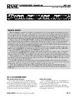
AC 22:
Mono 3-Way Configuration
1. POWER SWITCH:
Self-evident.
2. POWER INDICATOR:
When this yellow LED is lit, all output muting circuits are fully"on"
and the unit is ready to operate.
3. CH. 1 MASTER LEVEL CONTROL:
This controls the overall level without altering the
relative settings of the Hi, Mid and Low outputs.
4. LOW FREQUENCY LEVEL CONTROL:
This controls the level of signal going to the Low
Frequency driver.
5. LOW FREQUENCY MUTE SWITCH:
When pressed to the IN pos1t1on, all signal is
removed from the Low Frequency output. This eases tune-up procedure, as described in
Section 111-4.
6. LOW FREQUENCY TIME DELAY CONTROL:
This control adds from Oto 2mS of time
delay to the Low Frequency output only. This allows a low frequency driver to be electronically
phase-aligned with a high frequency driver whose diaphragm is situated BEHIND the low
frequency diaphragm. Refer to Section 111-3 for alignment procedure.
7. CROSSOVER FREQUENCY SELECTOR:
This 41-detent selector determines the cross
over frequency between low and mid frequency drivers. The detents will assure maximum
accuracy and consistency between channels. Refer to Section 111-2 to determine proper
crossover frequency for your particular system.
8. MID FREQUENCY LEVEL CONTROL:
This controls the level of signal going to the Mid
Frequency driver.
*
NOTE: The Ch. 1 High frequency level control and the Ch. 2 Master level control are
automatically bypassed internally when the AC 22 is connected as shown by the diagram on the
�p�ge. Adjusting these controls will have no effect in the Mono mode.
�/' ... .>
9. MID FREQUENCY MUTE SWITCH:
When pressed to the IN position, all signal is removed
from the Mid Frequency output. This eases tune-up procedures, as described in Section 111-4.
10. MIO FREQUENCY TIME DELAY CONTROL:
This control adds from Oto 2mS of time
delay to the Mid Frequency output only. This allows a mid frequency driver to be electronically
phase-aligned with a high frequency driver whose diaphragm is situated BEHIND the mid
frequency diaphragm. Refer to Section 111-3 for alignment procedure.
11. CROSSOVER FREQUENCY SELECTOR:
This sets the crossover frequency between the
Mid and High Frequency drivers. Refer to Section 111-2.
12. HIGH FREQUENCY LEVEL CONTROL:
This controls the level of signal going to the High
Frequency driver only.
6
Содержание AC 22
Страница 1: ...lo AC 22 and AC 23 ACTIVE CROSSOVERS OPERATING AND SERVICE MANUAL IIANE C OR P OR A T I O N ...
Страница 2: ......
Страница 3: ......
Страница 4: ......
Страница 5: ......
Страница 9: ......
Страница 15: ......
Страница 17: ......
Страница 20: ......
Страница 21: ......
Страница 23: ......
Страница 24: ......
Страница 25: ......
Страница 26: ......
Страница 27: ......


