background image

4-3

SpycerBox Cell | Hardware Guide | Version 1.0

Rohde & Schwarz DVS GmbH

Operation



R&S DVS SAN Remo

4.2  R&S DVS SAN Remo

R&S DVS’s configuration management software SAN Remo can be 
used to configure, reboot and shut down the SpycerBox Cell. It is in-
stalled on every SpycerBox Cell as standard.

SAN Remo will run in the web browser (Mozilla Firefox version 4 and 
higher, Internet Explorer version 11 and higher, Google Chrome and Sa-
fari) on every client in the network. The address is either the localhost 
(

127.0.0.1

) or the IP address of the SpycerBox Cell in the network as 

shown in the display in the middle of the faceplate (see section “Face-
plate” on page 2-4). After 
starting it, you have to enter a user name (de-
fault: 

admin

) and password (default: 

admin

).

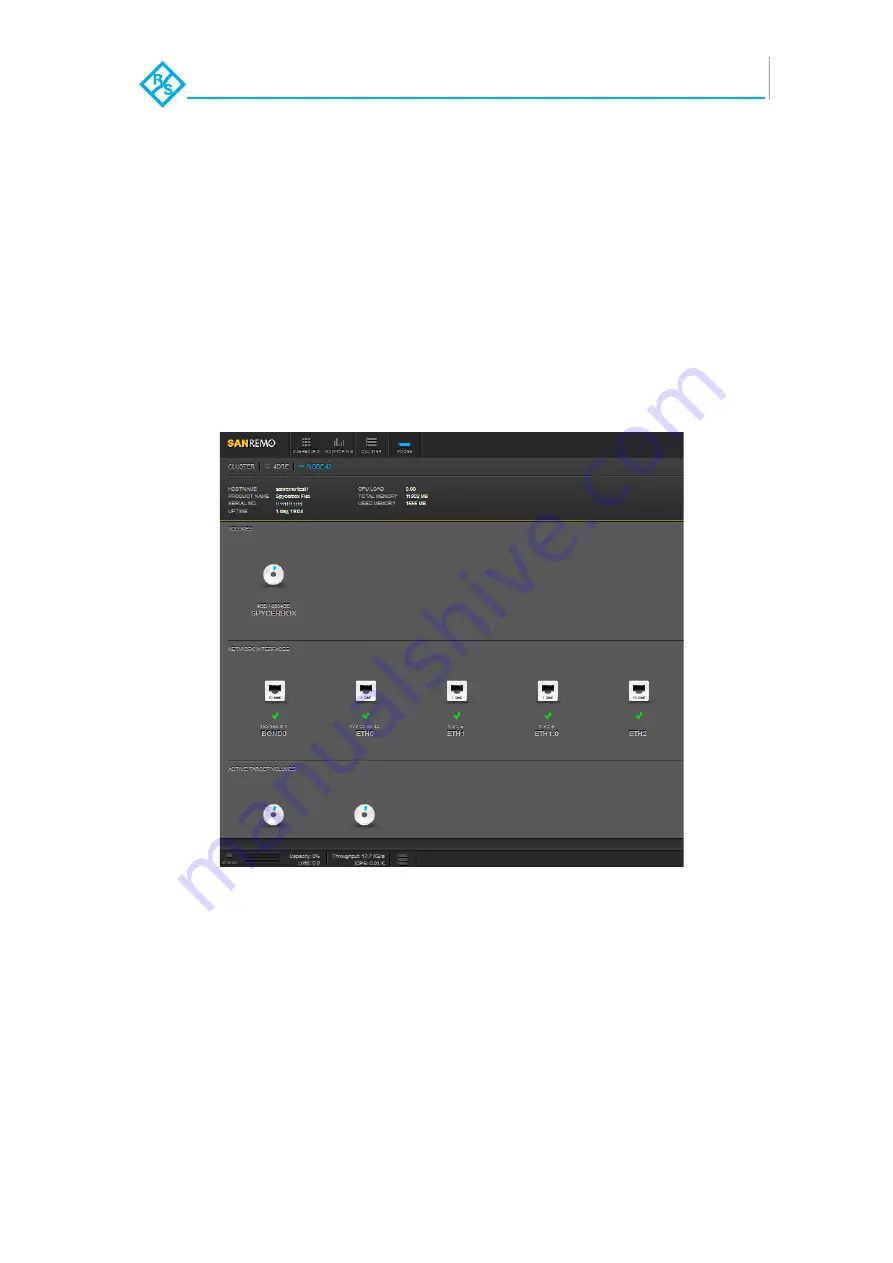
Figure 4-2: Plugin view in the SAN Remo software

With SAN Remo you can change the configurations of the R&S DVS 
system (e.g. its IP address or Fibre Channel connections). Select the 
system represented by a node and click on the respective icon to view 
and change the settings. Afterwards you will see all options that can be 
changed. With the monitoring feature you can obtain a graphical over-
view of certain properties of different nodes.

SAN Remo can also be used to gather log files of the system, for exam-
ple, for troubleshooting. By default they will be saved in a single archive 
file on the desktop of your system.

Содержание SpycerBox Cell

Страница 1: ...SpycerBox Cell Hardware Guide Version 1 0 Storage Solution R S SpycerBox Cell Hardware Guide...

Страница 2: ...SpycerBox Cell Hardware Guide Version 1 0 Rohde Schwarz DVS GmbH...

Страница 3: ...We offer no guarantee that this documentation is correct and or complete In no event shall Rohde Schwarz DVS GmbH be liable for any damages whatsoever including without limitation any special indirect...

Страница 4: ...GmbH Headquarters Support Rohde Schwarz DVS GmbH Krepenstr 8 30165 Hannover GERMANY Phone 49 511 67807 0 Fax 49 511 630070 E mail info dvs rohde schwarz com Internet http www dvs de Phone 49 511 67807...

Страница 5: ...2 1 Variants of the SpycerBox Cell 2 2 2 2 Overview of the Front 2 3 2 2 1 Faceplate 2 4 2 2 2 Hard Disk Tray 2 6 2 3 Overview of the Rear 2 8 2 3 1 Power Supply 2 9 2 3 2 Controller Module 2 10 2 3...

Страница 6: ...nance 5 13 5 4 Power Supply Maintenance 5 19 5 5 Backup or Recovery of the System Disk 5 21 5 5 1 Creating a Backup Image of the System Disk 5 21 5 5 2 Restoring the System Disk 5 23 A Appendix A 1 A...

Страница 7: ...his User Guide The following typographical conventions will be used in this documen tation 1 Texts preceded by this symbol describe activities that you must perform in the order indicated Texts preced...

Страница 8: ...marks are references to other manuals guides chapters or sections Texts enclosed by single quotation marks are references to labelings given by the author and quoted labelings Window Text in bold wit...

Страница 9: ...ts The screenshots shown in this documentation may be taken on various operating systems as well as from pre release versions of the software Their appearance may differ from your environment However...

Страница 10: ...rounding the system Avoid touching the internal components of the R S system whenever possible Computer hardware contains components that are sensitive to changing voltages Connecting or disconnecting...

Страница 11: ...a lifting truck Keep the R S system as a transportation good dry In the warranty period you have to keep the original packing and use it in case of transportation Environmental Conditions For error fr...

Страница 12: ...ss for the necessary repairs to be performed In the warranty period the customer must keep the original packing and pack the R S product in it in case of a product return If the customer is not satisf...

Страница 13: ...device free of charge to a waste disposal organization which will recy cle and reuse it environmental friendly General Notes Please observe the following general important notes Full storage In case o...

Страница 14: ...Introduction Important Notes 1 8 SpycerBox Cell Hardware Guide Version 1 0 Rohde Schwarz DVS GmbH...

Страница 15: ...e Schwarz DVS GmbH Overview Overview Variants of the SpycerBox Cell 2 2 Overview of the Front 2 3 Faceplate 2 4 Hard Disk Tray 2 6 Overview of the Rear 2 8 Power Supply 2 9 Controller Module 2 10 Expa...

Страница 16: ...SpycerBox Cell SATA enterprise or with SAS interface The following options are available Ethernet Option Fibre Channel Option No additional Ethernet option only 1 1 Gbit s onboard Quad port Ethernet...

Страница 17: ...or backup ma terial All disks can be replaced easily in case of failure The disk array is described in more detail in section Hard Disk Tray on page 2 6 illuminated display The display is illuminated...

Страница 18: ...p turns the system on or off The respective state of the system will be indicated by the R S DVS logo in the middle of the faceplate see section Faceplate on page 2 4 mute In case of a hardware malfun...

Страница 19: ...rate but intense strength from the right side to your direction 3 Take the faceplate out of its fastening on the left side Then you can access the hard disks of the hard disk tray see section Hard Dis...

Страница 20: ...he hard disk trays Figure 2 3 Hard disk tray Each hard disk of the array is connected to the system with the help of a disk carrier which makes the removal of a hard disk from the system easy Further...

Страница 21: ...pes and options lever The lever can be used to pull the disk carrier and its hard disk out of the system disk carrier The disk carriers hold each one hard disk of the array The hard disks are mounted...

Страница 22: ...gh power to keep the system operational Further information about the power supply can be found in sec tion Power Supply on page 2 9 controller module The controller module is an exchangeable unit con...

Страница 23: ...other one fails a continued operation of the sys tem cannot be guaranteed It is recommended to change a failed power supply unit im mediately see section Power Supply Maintenance on page 5 19 handle W...

Страница 24: ...The position of the individual panels on the controller module may vary and or other panels may be installed either for internal reasons or on your request The panels showing the Ethernet option and...

Страница 25: ...s FC Quad channel 16 Gbit s FC For further information about this please see section Variants of the SpycerBox Cell on page 2 2 fixed main connector panel This is the fixed part of the controller pan...

Страница 26: ...he USB 3 0 connector universal serial bus of fers you the possibility to transfer media e g to an R S DVS mobile storage quickly status LED This LED indicates the status of the controller module It gi...

Страница 27: ...er system It provides the following connections Figure 2 9 Expansion panel on rear of the SpycerBox Cell No Item Explanation 1 FO failover man agement Standard connector for the failover man agement N...

Страница 28: ...d by a battery backup unit If the system s operation gets interrupted for example in case of a power failure it will provide power to the cache of the con nected RAID controller so that buffered data...

Страница 29: ...3 1 SpycerBox Cell Hardware Guide Version 1 0 Rohde Schwarz DVS GmbH Installation Installation System Setup 3 2 Note about the Network Installation 3 3 Contents...

Страница 30: ...s operable at a resolution of at least 1280 1024 pixels default manufacturing setting 4 Connect any other peripheral computer equipment For an over view of the panels and connectors at the system s re...

Страница 31: ...R S DVS web page www dvs de you can find some diagrams showing how the SpycerBox Cell may fit in a workflow network To connect the R S DVS system to a network central storage you should have experien...

Страница 32: ...Installation Note about the Network Installation 3 4 SpycerBox Cell Hardware Guide Version 1 0 Rohde Schwarz DVS GmbH...

Страница 33: ...4 1 SpycerBox Cell Hardware Guide Version 1 0 Rohde Schwarz DVS GmbH Operation Operation Starting the System 4 2 R S DVS SAN Remo 4 3 Shutting Down the System 4 4 Contents...

Страница 34: ...r switch The system will be started and the R S DVS logo in the middle of the faceplate lights up As with any standard computer after initial booting the system begins to load the installed operating...

Страница 35: ...display in the middle of the faceplate see section Face plate on page 2 4 After starting it you have to enter a user name de fault admin and password default admin Figure 4 2 Plugin view in the SAN R...

Страница 36: ...the operating system the usual way see also section R S DVS SAN Remo on page 4 3 and section R S DVS SAN Remo on page 4 3 The operating system will then save your personal settings and once it has en...

Страница 37: ...onding anymore or not completely loaded perform the following Shut down the system by pressing the power switch until the sys tem turns off The system will then shut down immediately This procedure ca...

Страница 38: ...Operation Shutting Down the System 4 6 SpycerBox Cell Hardware Guide Version 1 0 Rohde Schwarz DVS GmbH...

Страница 39: ...nce 5 2 Introduction to RAID 5 2 Identifying a Broken Hard Disk 5 4 Replacing a Hard Disk 5 5 Fan Failure Management 5 10 Controller Maintenance 5 13 Power Supply Maintenance 5 19 Backup or Recovery o...

Страница 40: ...T world has defined several levels of RAID most of them providing some kind of data protection The RAID feature makes the R S DVS system tolerant of disk failures Even with a broken disk operations ca...

Страница 41: ...AID array in the SpycerBox Cell These are connected to the RAID controller that ap plies a RAID 5 to the data With this the data is striped across these hard disks during write procedures At the same...

Страница 42: ...hard disk or disk carrier related error see section Hard Disk Tray on page 2 6 An alarm can be caused by a number of reasons Please refer to section Troubleshooting on page A 2 first for further deta...

Страница 43: ...emo Configuration Management supple ment If the first hard disk tray does not contain any broken hard disk slide it back into the system and pull the second hard disk tray out Second disk fail If you...

Страница 44: ...er 2 Use the lever to cautiously pull the disk carrier out of the system For this take the lever pull the disk carrier cautiously to your direc tion when standing right in front of the system and then...

Страница 45: ...hen standing right in front of the system you have to cautiously slide the hard disk back in its place on the hard disk tray The interfaces at the hard disk have to plug back in place on the hard disk...

Страница 46: ...nce Hard Disk Maintenance 5 8 SpycerBox Cell Hardware Guide Version 1 0 Rohde Schwarz DVS GmbH Figure 5 4 Sliding the hard disk back in 3 Then simply move the lever back down Figure 5 5 Moving down th...

Страница 47: ...operational again The disk carrier of the replaced disk should be level with the others of the array The respective LED on the hard disk will show you its state and therefore a successful reassemblin...

Страница 48: ...into two steps 1 Removing the faceplate with the broken fan s from the system 2 Fastening the faceplate to the system An alarm can be caused by a number of reasons Please refer to section Troubleshoot...

Страница 49: ...per cooling of your system cannot be guaranteed Replace a faceplate with a broken fan as soon as possible The system must be operated only with the faceplate installed to ensure proper cooling In case...

Страница 50: ...section Faceplate on page 2 4 Having fastened the faceplate no alarm should be sounded anymore Other spare parts Others than the original manufacturer spare parts might damage your system Only use ori...

Страница 51: ...roller module into the system Incorrect maintenance Incorrect exchange of the controller module can cause damages to the system Before exchanging the controller module contact the R S DVS service depa...

Страница 52: ...dule and you can cautiously pull it down as shown in the figure below Incorrect packaging When sending hardware parts back to R S DVS incorrect packag ing like too small boxes or missing padding may d...

Страница 53: ...Use the anchoring to cautiously pull the controller module out of the system Figure 5 9 Pulling out the controller module Incorrect handling of the controller module Significant environmental changes...

Страница 54: ...the follow ing 1 Cautiously slide the new controller module back into its shaft as in the following figure Figure 5 10 Sliding back the controller module 2 Push the anchoring up and fix the locking s...

Страница 55: ...n Arrays are found Array Press Enter to accept the current configuration Press Ctrl A to enter Adaptec RAID Configuration Utility Press Ctrl H to Pause Configuration Messages Default i s not to accept...

Страница 56: ...iguration Then you have to specify the boot device in the BIOS of the RAID To access the RAID BIOS press Ctrl H at the indicated moment during the start up of the system The setting can be found after...

Страница 57: ...w of the Front on page 2 3 Each power supply unit in the R S DVS system is hot swappable so you can safely replace it with the system running Follow these steps to replace a power supply unit 1 Take a...

Страница 58: ...ith this the power supply unit has been replaced successfully High voltages The system you are working on operates with voltages that can be hazardous to your health Do not reach inside the system whe...

Страница 59: ...the Rear on page 2 8 3 Turn on or restart the R S DVS system and at the indicated moment during start up press F11 on your keyboard to enter the boot menu Selecting wrong source device For example se...

Страница 60: ...o the USB press 1 and then Enter on your keyboard Afterwards a list of possible source devices will be detailed on the screen In a SpycerBox Cell the system drive normally will be sdc but on special s...

Страница 61: ...ard disk To abort the process at this point enter n for no and press Enter on your keyboard You will be redirected to the DVS Rescue script After starting the process a termination is not possible any...

Страница 62: ...Once the loading has finished you will see the DVS Rescue script with its options on the screen Your display should look similar to the follow ing DVS Rescue 1 Backup on USB device 2 Restore from USB...

Страница 63: ...process type in y for yes and press Enter on your keyboard The program will now start the recovery process Its progress will be in dicated on the screen When the system has finished the recovery proc...

Страница 64: ...Maintenance Backup or Recovery of the System Disk 5 26 SpycerBox Cell Hardware Guide Version 1 0 Rohde Schwarz DVS GmbH...

Страница 65: ...S GmbH Appendix Appendix Troubleshooting A 2 Technical Data A 5 General Technical Data A 5 Dimensions A 6 Packing Instructions A 7 Conformity Declarations A 9 RoHS Compliance A 9 EC Declaration of Con...

Страница 66: ...If this is not successful con tact the R S DVS service depart ment A RAID controller is defective If you can rule out the above men tioned causes a RAID controller may be defective Before attempting t...

Страница 67: ...entioned cause a power supply unit has failed Replace the broken unit as described in section Power Supply Mainte nance on page 5 19 A fan has failed Check the LEDs of the power supply units If all ar...

Страница 68: ...l all disk carriers partial ly out of the chassis and afterwards install them again See to it that they are pulled out and reassembled cor rectly as described in section Re placing a Hard Disk on page...

Страница 69: ...uip ment Measured with SpycerBox Cell i7 3615QE 2 3 GHz 16 GB RAM Cap 30 Seagate ST9600204SS 1 Atto FC Celerity FC 162E Chassis weight Approx 22 kg Chassis weight with drives Approx 28 kg Environment...

Страница 70: ...ns of the R S DVS system The drawing already includes some space for connectors and plugs that can protrude from the rear plug safety l minus j usually plus 150 mm However this amount of space depends...

Страница 71: ...S DVS de vice in the original packing You have to keep the original packing and use it in case of transportation In any other case if you do not have the original packing anymore use a similar struct...

Страница 72: ...Appendix Packing Instructions A 8 SpycerBox Cell Hardware Guide Version 1 0 Rohde Schwarz DVS GmbH Figure 3 Pack accessories Figure 4 Close box A...

Страница 73: ...of Conformity CE Marking Rohde Schwarz DVS GmbH herewith declares that the following product s according to the provisions of the mentioned EC Directives including their relevant revisions at the time...

Страница 74: ...digital device pursuant to part 15 of the FCC Rules These lim its are designed to provide reasonable protection against harmful inter ference when the equipment is operated in a commercial environment...

Страница 75: ...eclaration of conformity 1 7 A 9 dimensions A 6 disk carrier 2 6 2 7 5 6 disk set RAID pack 5 2 disk tray see hard disk tray or system disk tray DisplayPort 2 11 DVI connector 2 12 DVS Rescue 5 22 5 2...

Страница 76: ...se 3 2 mute button 2 4 5 10 5 19 A 3 A 4 N network connection possibilities 2 10 installation 3 3 network connector 2 11 notes important 1 6 1 7 O operation items 2 4 overheating A 3 overview front 2...

Страница 77: ...ants 2 2 SpycerBox Cell version SAS version 2 2 SATA enterprise or with SAS interface 2 2 SSD version 2 2 starting 4 2 status of hard disks 2 7 of power supply unit 2 9 of power on off 2 4 storage cap...

Страница 78: ...Index I 4 SpycerBox Cell Hardware Guide Version 1 0 Rohde Schwarz DVS GmbH...

Отзывы: