


Putting into Operation
R&S NRT-Z43/Z44
1081.1309.02 1.2
E-8
CAUTION
Do not exceed permissible continuous loading (see diagram on the rear).
Switch sensor into test circuit only with the RF power switched off.
Tighten RF connector by hand.
Non-observance may cause injuries, i.e. skin burns, damage to the instruments used
and premature wear of the RF connectors.
1.3 Connecting the Sensor to the R&S NRT Power Reflection
Meter
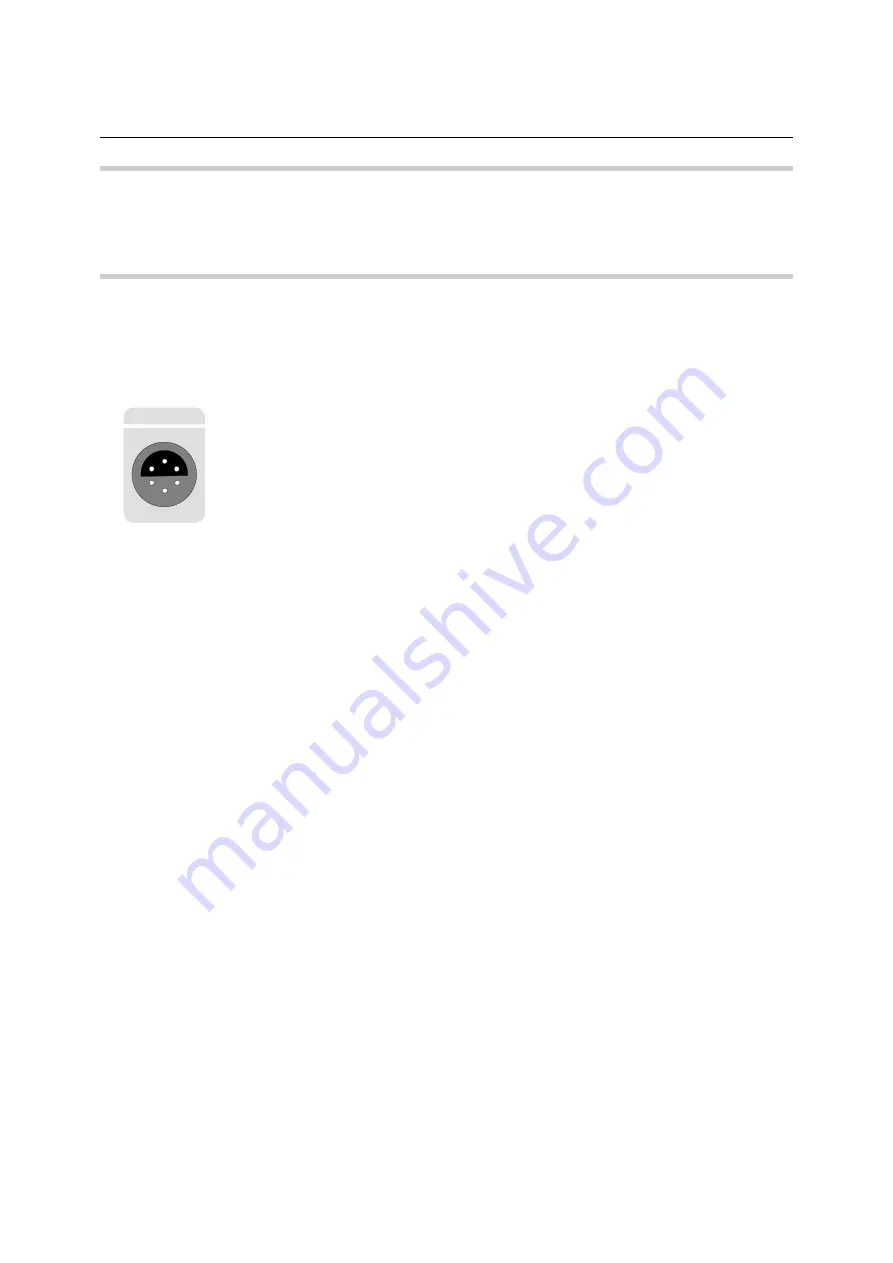
SENSOR
The sensor can be connected to the
SENSOR
connector on the front panel of the
R&S NRT or to the
SENSOR 2
or
SENSOR 3
connector on the rear panel (only with
option R&S NRT-B2). The R&S NRT should recognize the sensor in an initialization
routine a few seconds after the connection is made or after power-up, respectively,
and immediately start measurements.
Operation of the R&S NRT is described in detail in the associated operating manual.
1.4 Operating the Sensor on a PC via the R&S NRT-Z5
USB In
terface Adapter
To operate the sensor on a PC via the R&S NRT-Z5 USB interface adapter, the following requirements
must be met:
The PC must have a USB port that can supply current of 500 mA. To be on the safe side, you can
determine the current available on the USB ports as follows:
•
Select
Control Panel
or
Settings – Control Panel
in the Windows™ start menu
•
Select the
System
icon
•
Select the
Hardware
tab
•
Click the
Device Manager
button to start the device manager
•
Open the
Universal Serial Bus controllers
item (listing all USB controllers, hubs and USB de-
vices)
•
Double-click
USB Root Hub
(or right-click and select
Properties
in the context menu)
•
Select the
Power
tab: If the hub is self-powered and the total power available indicated under
Hub information
is 500 mA per port, the R&S NRT-Z5 can be safely operated.


