35
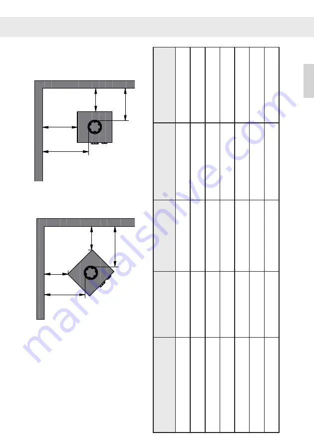
MINIMUM CLEARANCE
Rear Vent
A: Side Wall to Unit
20” (508 mm)
20” (508 mm)
B: Back Wall to Unit
9” (229 mm)
10” (254 mm)
C: Corner Wall to Unit
11” (279 mm)
11” ( 279 mm)
D: Celing Height
56” (1422 mm)
56” ( 1422 mm)
E: Back Wall to Vent Pipe
13.7” ( 349 mm) 14.7” ( 374 mm)
F: Side Wall to Vent Pipe
25.7” ( 653 mm) 25.7” ( 653 mm)
G: Corner Wall to Vent Pipe
19.2” ( 486 mm) 19.2” ( 486 mm)
Front Wall - Furnishing
36” ( 915 mm)
36” ( 915 mm)
A
B
E
F
C
G
C
G
D
**
8"
2"
8"
8"
16
"
A
B
E
F
C
G
C
G
D
**
8"
2"
8"
8"
16
"
A
B
E
F
C
G
C
G
D
**
8"
2"
8"
8"
16
"
A
B
E
F
C
G
C
G
D
**
8"
2"
8"
8"
16
"
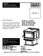
Manufactured by:
RAIS A/S
Industrivej 20, DK-9900
Frederikshavn, Denmark
Rev: 5
Januar 23 - 2024
Model:
NEXO 100, 120, 140, 160, 185 USA
Solid Fuel Room Heater, For Use With Solid Wood Fuel Only
Emission Report no.
:
0138WS017E
Safety Report:
23-204
Model
Date of manufacture Month
Year
Serial no.
Made in Denmark
Tested to:
UL 1482-2022
Clearances to combustible surfaces
Parallel wall installation
Back wall
Side wall
Corner wall installation
Adjacent wall
Adjacent wall
** Rear/T
op vent option
Ceiling
Floor Protector
FLOOR PROTECTION:
Floor protection must be non-combustible material extending beneath the
stove, and to the front and sides from door opening and to the rear as indi-
cated. The floor protection is not required to have thermal protection (R=0)
Replace glass with only Rais authorized dealer supplied
ceramic glass
** Not Tested - NFPA Guidelines in USA,
U.S. ENVIRONMENTAL
PROTECTION AGENCY
Certified to comply with 2020
particulate emission standards using
crib wood. 1.1 g/hr, Method 28R
This wood heater needs periodic inspection and repair for proper operation.
Consult the owner’s manual for further information. It is against federal
regulations to operate this wood heater in a manner inconsistent with the
operating instructions in the owner’s manual.
** Non testé - NFPA Guidelines au USA
The appliance must not be installed in a factory-built
fireplace.
See further floor protection requirements
at bottom left corner of this label.
Floor protector must be under the pipe and 2”
(5cm) beyond each side for back venting.
Front
US
INSTALLATION
Minimum Clear
ance
Single W
all
V
en
t Pipe
Double W
all
V
en
t Pipe
With Swiv
el Base
10-0000-
1501
Back
W
all
Flue Exit
A: Side
W
all
to Unit
20” / 508 mm
20” / 508 mm
36” / 915 mm
20” / 508 mm
B: Back
W
all
to Unit
9” / 229 mm
9” / 229 mm
36” / 915 mm
10” / 254 mm
C: Corner
W
all
to Unit
11” / 279 mm
11” / 279 mm
36” / 915 mm
11” / 279 mm
D: Ceiling fr
om
V
en
t Pipe
56” / 14
22 mm
56” / 14
22 mm
56” / 14
22 mm
56” / 14
22 mm
E: Back
W
all
to
V
en
t Pipe
13.
7” / 349 mm
13.
7” / 349 mm
40
.7” / 1034 mm
14.
7” / 3
74 mm
F: Side
W
all
to
V
en
t Pipe
25.
7” / 653 mm
25.
7” / 653 mm
41.
7” / 1059 mm
25.
7” / 653 mm
G: Corner
W
all
to
V
en
t Pipe
19
.2” / 486 mm
19
.2” / 486 mm
44.2” / 1123 mm
19
.2” / 486 mm
INSTALLATION


