Appendix 3 – Autoflush Module – Page
2
Electric Wiring
•
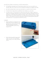
Red (+ positive) & black (- negative) wires from the Rainman flush timer connect to 12V or 24V.
•
Blue and green wire from the Rainman flush timer is fitted to the two pin Deutsch connector.
•
Connect the Deutsch plug into the mating socket fitted to the motorised valve.
•
The mounting feet of the timer can be positioned anywhere along the side slot. Relax the retaining screw
and slide the foot along the side slot.
•
When supplying power to the Rainman flush timer, consideration should be made for power shutdown
when disabling your system. For example, it may have its own circuit or be wired to your fresh water pump
circuit.
Plumbing
•
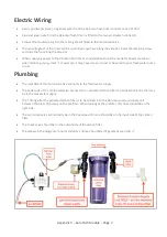
The inlet side of the motorised valve connects to the fresh water supply.
•
The outlet side of the motorised valve connects to an activated carbon filter to neutralise chlorine that may
be in the tank water supply.
•
The T fitting after the activated carbon filter is to be spliced in to the Rainman pressure supply unit
between the brass lift pump and the prefilter. When looking at the prefilter, this hose should be on the
right side.
•
The motorised valve will normally be in the closed position and should be on the input side of the carbon
filter.
•
The check valve should be on the output side of the carbon filter.
•
The elbows in the diagram are not mandatory and may be omitted if geometry warrants it.

