background image

Weather Station - Model “PRO”

Nov.,  2001                                                        Page 

28


Model “PRO”- Weather Station

Cozz                                                                                                                                                       GT27145B

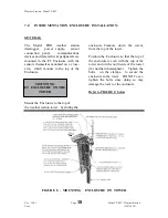
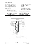
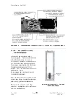
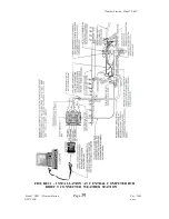
Refer  to  FIGURE  13  below:

On the bottom of the Cross-Arm,  on the
end where the wind sensor has been
installed,  remove the two screws for the
Relative Humidity/Temperature sensor
Radiation Shield.

Un-tape the RH/Temperature sensor
from the bottom of the Cross-Arm.

Remove the “yellow” protective plastic
cap from the end of the sensor,  by
slipping it off the end of the sensor.
This can be discarded as it will not be
used.

Insert the RH/Temperature sensor into
the end of the shaft of the Radiation
Shield.   Insert it to a depth where it is
securely seated.   Now secure the
Radiation Shield to the bottom of the
sensor Cross-Arm with the two (2)
screws you have previously removed.

FIGURE 13  -  TEMPERATURE/RH  SENSOR  INSTALLATION  DETAIL

INSTALLATION  OF  SOLAR
RADIATION PYRANOMETER:

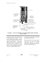
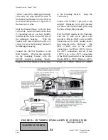
Refer to FIGURE 14 below:

Содержание Pro

Страница 1: ...RAIN BIRD Weather Station Model PRO INSTALLATION MAINTENANCE AND TROUBLESHOOTING MANUAL November 2001 GT27145B...

Страница 2: ......

Страница 3: ...ation 5 Prompts from Geomag 7 4 0 Weather Station Concrete Base 9 Supplied Components 9 Installer Supplied 9 Tools Required 9 Installation 9 5 0 External Wiring to Weather Station 12 Wiring Valve Acce...

Страница 4: ...Radiation Shield 28 Installation of Solar Radiation Pyranometer 29 Sensor Cable Connections 30 Configure Sensor Switch Settings 31 Upgrading a JR weather station to a PRO 31 Sensor Verification and Cl...

Страница 5: ...ty Sensor 45 Temperature Sensor 46 Other Maintenance 46 Seal of ET Enclosure 46 Battery Check 47 Sensor Testing 47 Wind Speed Sensor 48 Wind Direction Sensor 48 Solar Radiation Sensor Pyranometer 48 T...

Страница 6: ...999 Stored in Final Storage 53 Using a Laptop Computer 53 Checking the Communications Wire Path 54 Loop Resistance 54 Ground Resistance 54 WS PRO SH Direct Connect Weather Station 54 Weather Station w...

Страница 7: ...45B Cozz Appendix Description Page Upgrading the Model JR Weather Station to a Model PRO Weather Station 60 Typical 3 Rod Grounding Grid 60 Ground Resistance 61 Bentonite Contact 61 Rocky Conditions 6...

Страница 8: ...External Wiring Detail at the PRO PH Station 17 8 Mounting ET Enclosure on Tower 18 9 16VAC Connection Rechargeable Battery Installation 20 10 Solar Pane Installation Detail 23 11 Cross Arm Mounting D...

Страница 9: ...allation at Central Computer for Telephone Connected Weather Station 41 23 Using the ML 10 KD Keyboard Display 50 24 Configuration of Serial Cable 53 25 Test of Short Haul Modem 55 26 Test of Communic...

Страница 10: ......

Страница 11: ...r MAXI Cirrus software subjects the climatic information that it gathers to a version of the modified Penman Equation The Penman Equation has been proven through over 35 years of university research t...

Страница 12: ...12 20 Matr l for Concrete Base Form 4 12 Wood Stakes 1 2 x 4 x 10 piece of wood 8 8p double head nails 8 16p double head nails 20 ft of form wire yard of concrete 6 Ft Step Ladder Concrete trowel edg...

Страница 13: ...r station should be eight 8 to ten 10 feet above the turfgrass Remember that the roof of a building IS NOT a good site for the weather station The weather station does NOT need to be hidden The Rain B...

Страница 14: ...diation and adequately ventilated Situations to avoid include large industrial heat sources rooftops steep slopes sheltered hollows high vegetation shaded areas top of a hill bottom of a swale swamps...

Страница 15: ...ic compass and applying the correction for magnetic declination Other methods employ observations using the North Star or the sun and are discussed in the Quality Assurance Handbook for Air Pollution...

Страница 16: ...Weather Station Model PRO Nov 2001 Page 6 Model PRO Weather Station Cozz GT27145B FIGURE 2 MAGNETIC DECLINATION FOR THE CONTIGUOUS UNITED STATE...

Страница 17: ...settings No parity 8 data bits and 1 stop bit i e N81 Telephone numbers Phone Number Baud Rates 303 273 8672 2400 303 273 8673 1200 303 273 8678 1200 Upon carrier signal detection press Return once o...

Страница 18: ...g out If you used one of the commercial numbers the GLDSV1 prompt will reappear Type LO to disconnect Use of GEOMAG is free except for telephone charges If possible please avoid using GEOMAG between 9...

Страница 19: ...h a 24 square top and slanting outward sides to the bottom of 32 square The Sloping sides of the foundation are very IMPORTANT in providing the necessary support to the weather station tower in preven...

Страница 20: ...emplate and elbow attach the wire securely to the nail Repeat this same process with the other piece of form wire going to the opposite nails and further securing the template elbow and anchor bolts i...

Страница 21: ...ther Station Model PRO Model PRO Weather Station Page 11 Nov 2001 GT27145B Cozz FIGURE 4 CONCRETE BASE DETAIL FIGURE 5 ANCHOR BOLT TEMPLATE DETAIL 5 0 EXTERNAL WIRING TO WEATHER STATION Refer to FIGS...

Страница 22: ...open spade connectors clad ground rod one of a 3 rod grounding grid NOTE The minimum voltage to the transformer shall be not less than 112 volts Wire sizing shall be in accordance with the chart give...

Страница 23: ...and the GREEN XMT wires of the communication cable furnished with the weather station and marked P N 9720 ET SHORT HAUL COMM The RED RCV BLACK RCV pair shall be connected to the RED BLACK wires respec...

Страница 24: ...Weather Station Model PRO Nov 2001 Page 14 Model PRO Weather Station Cozz GT27145B FIGURE 6 EXTERNAL WIRING DETAIL AT THE PRO SH WEATHER STATION...

Страница 25: ...rect Burial connectors The splices for the phone line shall be made in the valve box where the power wiring splices are made and where the MGP 1 grounding plate assembly with an MSP 1 surge arrestor m...

Страница 26: ...ction of the tower Secure the cables at the top of the upper section with tape so that they cannot pull back down into the tower as you assemble the two tower sections Now assemble the upper tower sec...

Страница 27: ...Weather Station Model PRO Model PRO Weather Station Page 17 Nov 2001 GT27145B Cozz FIGURE 7 EXTERNAL WIRING DETAIL AT THE PRO PH WEATHER STATION...

Страница 28: ...to the top of the Enclosure MOUNTING ET ENCLOSURE TO THE TOWER enclosure brackets down the tower from the top of the tower Position the Enclosure so that the top of the enclosure is even with the top...

Страница 29: ...LY important to give maximum protection to the weather station against damage from lightning surges This connection should be INSPECTED on a regular basis to assure it remains tight and making good co...

Страница 30: ...lots in it over the upper two 2 screws Line up the battery bracket slotted holes in the other end of the bracket with the two 2 lower screws Now push down on the battery seating the bracket in place w...

Страница 31: ...the cap on the Heyco fitting to seal around the cable The wires can be attached to these connectors by depressing the lever on the connector for each wire and while doing so insert the stripped end o...

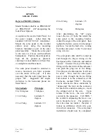
Страница 32: ...es 46 to 65 deg Latitude 15 degrees 65 deg 80 degrees After determining the tilt angle loosen the two 2 bolts that attach the solar panel to the mounting bracket Adjust the angle of the solar panel th...

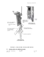
Страница 33: ...Weather Station Model PRO Model PRO Weather Station Page 23 Nov 2001 GT27145B Cozz FIGURE 10 SOLAR PANEL INSTALLATION DETAIL 8 0 INSTALLATION OF INSTRUMENTATION...

Страница 34: ...ors on the back of the back panel of the ET Enclosure SUPPLIED COMPONENTS 1 Sensor Cross Arm 1 Met One 034A Wind Sensor 1 034A Mounting Shaft 1 Radiation Shield INSTALLATION OF CROSS ARM TO ET ENCLOSU...

Страница 35: ...Weather Station Model PRO Model PRO Weather Station Page 25 Nov 2001 GT27145B Cozz FIGURE 11 CROSS ARM MOUNTING...

Страница 36: ...de of the mounting shaft and re installing the aligning screw Next loosen the set screw in the top of the 034A wind sensor the seet screw opposite the one securing the wind direction point Place the e...

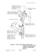
Страница 37: ...Weather Station Model PRO Model PRO Weather Station Page 27 Nov 2001 GT27145B Cozz FIGURE 12 WIND SENSOR INSTALLATION DETAIL INSTALLATION OF RELATIVE HUMIDITY TEMPERATURE SENSOR AND RADIATION SHIELD...

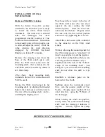
Страница 38: ...oss Arm Remove the yellow protective plastic cap from the end of the sensor by slipping it off the end of the sensor This can be discarded as it will not be used Insert the RH Temperature sensor into...

Страница 39: ...mounted at the factory on a mounting bracket at the opposite end of the cross arm near the Tipping Rain Bucket gage By using the three 3 leveling screws level the Pyranometer After leveling remove th...

Страница 40: ...ation 10105 cable connect to 3 connector labeled SOLAR RADIATION Rain 10094 cable connect to 5 connector labeled RAIN PRECIP Temp RH 10090 cable connect to 1 connector labeled TEMP RH WD WS Wind Direc...

Страница 41: ...ON TO A PRO MODEL Refer to FIGURE 17 below By means of the UPGRADE KIT a Model JR Rain Bird weather station can be upgraded to a Model PRO weather station On the top of the Enclosure of the existing m...

Страница 42: ...ounting bracket and the support bracket Turn each screw two 2 or three 3 turns into the threaded holes Install the sensor cross arm to the top of the Enclosure as previously described All other sensor...

Страница 43: ...at the weather station is normally installed at the factory in the ET Enclosure The Short Haul Modems enable communication between the datalogger and the central computer over two 2 twisted pairs of...

Страница 44: ...RAD Modem Position this assembly on the mounting bracket with the SC932C Interface pointing down Strap the SC932C Interface unit securely to the mounting bracket using the Velcro strap Connect the SC...

Страница 45: ...nuts Taking the phone modem and bracket assembly install the two keyhole slots in the bracket over the top two 2 screws that you have previously installed in the datalogger housing Be sure the open sl...

Страница 46: ...of condensation on the instrumentation Desiccant should be changed when the internal Enclosure humidity sensor measures 30 or higher Install the desiccant as shown in FIGURE 21 below Keep unused desi...

Страница 47: ...wire to the upper right connector connect the RED RCV wire to the lower right connector and the BLACK RCV wire to the lower left connector of the surge arrestor box Just outside the building of the c...

Страница 48: ...e and an aluminum shield with an outer insulation for direct burial shall be run underground form the central location valve box out to the weather station location At the valve box at the central loc...

Страница 49: ...Weather Station Model PRO Model PRO Weather Station Page 39 Nov 2001 GT27145B Cozz FIGURE 21 INSTALLATION AT CENTRAL COMPUTER FOR DIRECT CONNECTED WEATHER STATION...

Страница 50: ...o the Weather Station In addition the telephone company also furnishes surge protection on their lines Therefore no additional surge protection is required upon installation of the Weather Station STA...

Страница 51: ...Weather Station Model PRO Model PRO Weather Station Page 41 Nov 2001 GT27145B Cozz FIGURE 22 INSTALLATION AT CENTRAL COMPUTER FOR TELEPHONE CONNECTED WEATHER STATION...

Страница 52: ...entative maintenance steps will optimize battery life and decrease the chances of datalogger failure BATTERIES RECHARGEABLE Rechargeable power supplies should be connected to an AC transformer or unre...

Страница 53: ...Calibrate the Pyranometer some suggest yearly Replace RH chip in Air Temp RH Sensor Calibrate the Tipping Bucket Rain Gage To check accuracy of the rain gage 16 ounces of fluid is equal to 1 of rainf...

Страница 54: ...umber of turns or partial turns Rotation clockwise increases the number of tips per 16 ounces of water counter clockwise rotation decreases the number of tips per 16 ounces of water One half turn of b...

Страница 55: ...nce a year They should move freely and react to a wind speed of 2 to 3 mph The bearings have a life expectancy of 3 to 5 years except in very high wind areas where their life may only be 1 year The be...

Страница 56: ...Water will affect the temperature readings so be sure no direct water is hitting the weather station from sprinklers in the area SEAL OF ET ENCLOSURE The seal on the panel assembly of the Enclosure fo...

Страница 57: ...eration Check the battery under these conditions to get an accurate actual battery voltage level Allow 2 hours after the battery AC recharge power has been disconnected for the battery to dissipate hi...

Страница 58: ...SOR PYRANOMETER Refer to schematic wiring diagram located in the Appendix FIGURE 30 The Solar Radiation Sensor Pyranometer should measure between 40 OHMS and 90 2 OHMS when checked with an Ohm meter b...

Страница 59: ...Is the RH reading bad If just the RH readings are bad then the RH chip most likely needs to be replaced New RH chips for replacement are available from your local Rain Bird Distributor AIR TEMPERATURE...

Страница 60: ...ehind the cable cover Refer to FIGURE 24 below Remove the cable cover Remove the cap from the Serial I O connector and plug the keyboard display cable into the connector FIGURE 23 USING THE ML 10 KD K...

Страница 61: ...ard continue with the next diagnostic problem below If you see NO display on the keyboard then there is NO power output from the datalogger of the weather station Pins 1 and 2 of the Serial I O connec...

Страница 62: ...th 6 followed by entering A to advance to the next location Continue to press A to check ALL locations of the datalogger If still no response to keypad input then continue with the next diagnostic pro...

Страница 63: ...ge format limitations are exceeded no number larger than 6999 in low resolution or 99999 in high resolution is stored Change the datalogger program USING A LAPTOP COMPUTER When a Laptop computer is be...

Страница 64: ...re initially connecting a direct connect or phone line weather station or when troubleshooting the weather station and the communication wiring is suspect check the communication wires for their integ...

Страница 65: ...Bird Weather Software go to the Main Menu and set the capital lock on the keyboard of the computer Be sure to configure a direct connect weather station Press a capital W from the Main Menu screen If...

Страница 66: ...al W from the Main Menu screen If a security number is asked for use 6275 Choose a direct connect station and the screen will go BLANK Assuming you have connected the communication wires correctly at...

Страница 67: ...the positive side and the Tip the negative side Have someone call in and then measure the voltage across the phone line It should read 90 to 110 Volts AC The answer modem switch circuit requires 40 Vo...

Страница 68: ...serial port of the computer and verify that it is functioning correctly just as is required when troubleshooting MAXI or MAXICOM TESTING THE SHORT HAUL MODEM For the older weather stations which used...

Страница 69: ...200 or 2400 Smart Modem is being used to communicate with the Weather Station be sure the switch settings are as follows SW Setting Function 1 DOWN Ignores DTR 2 UP English word result codes SW Settin...

Страница 70: ...MODEL PRO WEATHER STATION The Model JR weather station can be easily converted to a Model PRO weather station by the use of the Upgrade kit This Upgrade kit gives the additional instrumentation of a...

Страница 71: ...6 below the finish grade The rods shall be tied together below grade with 10 gauge or larger bare copper wire The wire shall be attached to the rod using a brass clamp A separate brass clamp shall be...

Страница 72: ...he rod with the soil ROCKY CONDITIONS In areas where you are unable to drive a rod or to bore a hole for a rod you may need to consider laying the rods horizontal 12 inches or so below the surface on...

Страница 73: ...he end of the pipe and cover it with soil to finish grade MSP 1 PIPE SURGE ARRESTORS Each of the pairs of wires in the communication path between the central computer and the weather station shall be...

Страница 74: ...Weather Station Model PRO Nov 2001 Page 64 Model PRO Weather Station Cozz GT27145B FIGURE 28 TYPICAL 3 ROD GROUNDING GRID DETAIL...

Страница 75: ...Weather Station Model PRO Model PRO Weather Station Page 65 Nov 2001 GT27145B Cozz FIGURE 29 TESTING OF WIND SENSOR...

Страница 76: ...Weather Station Model PRO Nov 2001 Page 66 Model PRO Weather Station Cozz GT27145B FIGURE 30 TESTING OF SOLAR RADIATION SENSOR...

Страница 77: ...Weather Station Model PRO Model PRO Weather Station Page 67 Nov 2001 GT27145B Cozz FIGURE 31 TESTING OF RAIN GAGE...

Страница 78: ...Weather Station Model PRO Nov 2001 Page 68 Model PRO Weather Station Cozz GT27145B FIGURE 32 TESTING OF TEMPERATURE RELATIVE HUMIDITY SENSOR...

Страница 79: ...Weather Station Model PRO Model PRO Weather Station Page 69 Nov 2001 GT27145B Cozz FIGURE 33 TESTING OF AIR TEMPERATURE PROBE...

Страница 80: ......

Отзывы: