16
www.raider.bg
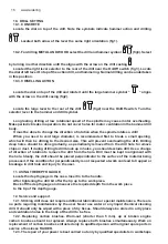
10. DRILL SETTING
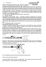
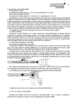
10.1. CONCRETE
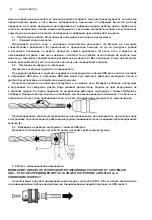
Locate the dial on top of the drill. Note the symbols indicate hammer action and drilling
. Located both arrow of the lever the same right orientation (fig1).
10.2. For drilling METAL AND WOOD select the drill and hammer symbol
(fig3). Select
by turning in either direction until the aligns with the arrow on the drill casting
Located the right lever selector to the rear of the drill near the On/Off switch (fig 3), Locate
the dial of left lever On top of the action drill, and hammering. Normal drilling can be undertaken
in this position.
10.3. CHISELLING ACTION
Locate the dial on top of the drill and rotate it until the large hammer symbol “
“ aligns
with the arrow on the drill casing (fig2).
Locate the large lever to the rear of the drill
(fig2) near the On/Off switch. Turn the
selector lever to the hammer and drill symbol.
Long lasting drilling at low rotational speed of the spindle may cause motor overheating.
Make periodic breaks in operation. Do not cover holes for motor ventilation in the hammer drill
body.
It must be done to change the direction of rotation when the spindle rotates a drill!
When you need to vent large diameter, is recommended first to break a small opening,
which will then be drilling to the desired size. This will prevent overloading the drill. Drilling
deep holes should be done gradually, as periodically removed from the drill hole to remove
chips or dust. If during drilling to drill block up in holes, you should exclude drill. Use a change
of direction of rotation to remove the drill from the hole. Drill must be kept in alignment with
the hole. Ideally, the drill should be placed perpendicular to the surface of the material being
processed. If the condition for perpendicularity is not respected at work can lead to trapped or
breakage in drill hole and injury to the user.
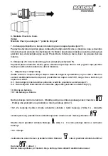
11. USING THE DEPTH GAUGE
Locate the depth gauge in the case. Insert in to the handle.
After tightening the drill bit offer the tip up to the work piece.
Back off the depth gauge and measure the required depth from the work piece
to the tip of the depth gauge.
12. Service and support.
12.1. Striking drill does not require additional lubrication or special maintenance. There are
no parts requiring maintenance by the user. Never use water or any liquid chemical cleaning
drill. It should only be wiped with a piece of dry tissue. Should always be stored in a dry place
and ventilation holes in the body of the drill to be free.
12.2. Replacing carbon brushes. Worn-out (shorter than 5 mm), up or broken engine
carbon brushes should be replaced. Always replace both brushes simultaneously. Work on
replacement of carbon brushes entrusted only to qualified person with original spare parts in
service of business RAIDER.
12.3. The repair of your power is best carried out only by qualified specialists in workshops
Содержание RD-HD37
Страница 3: ...3 ...
Страница 63: ...63 EXPLODED VIEW OF RD HD37 ...
Страница 78: ...78 www raider bg ...
Страница 81: ...81 ...
Страница 84: ...84 www raider bg ...
Страница 85: ...85 ...


