


Page:6
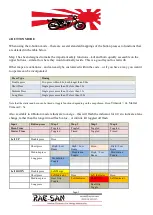
OUTPUTS
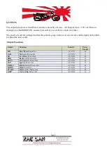
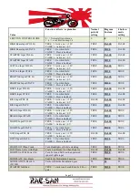
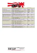
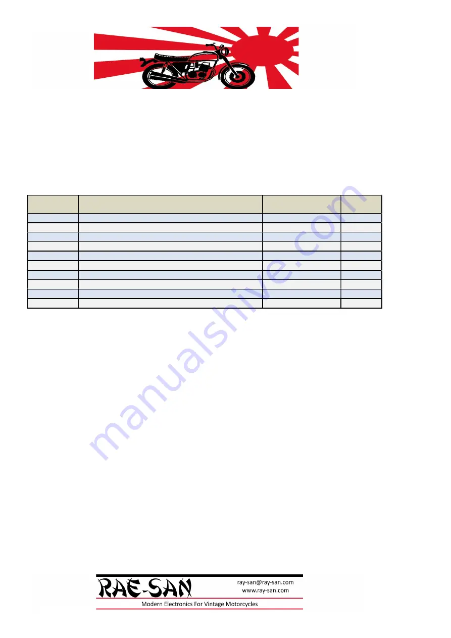
The output functions are listed below and are reasonably obvious – All Outputs drive +12V out when on
through 30A rated MOSFETS, and are protected by one of the two main 10A fuses -
The power circuits are arranged so that the ignition, grips, horn are on one circuit, and the lights on the other
to spread the load evenly.
Output Functions
Output
Function
Polarity
Power
Circuit
HB
H
igh
B
eam Power Out
+12V ON
B
TAIL
Tail
Light Power Out
+12V ON
A
LB
L
ow
B
eam Power Out
+12V ON
B
BRK
Br
a
k
e Light Power Out
+12V ON
A
LEFT
Left
Indicator Power Out
+12V ON
B
IGN
Ign
ition Power Out
+12V ON
A
RIGHT
Right
Indicator Power Out
+12V ON
B
HORN
Horn
Power Out
+12V ON
A
START
Start
er Relay Power Out
+12V ON
B
GRIP
Heated
Grip
Power Out
+12V ON
A
Содержание DRAFT D
Страница 1: ...V1 0 Bike Controller Module Installation Manual DRAFT D Rae San 31 10 2022...
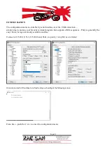
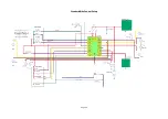
Страница 14: ...Custom control Setup Easiest approach...
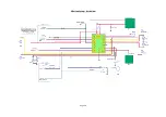
Страница 15: ...Page 15 Standard Bike Control Setup...
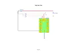
Страница 16: ...Page 16 4 Button Setup Active low...
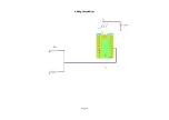
Страница 17: ...Page 17 Using Stock Fuses...
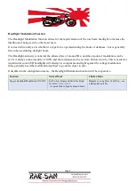
Страница 18: ...Page 18 Adding Heated Grips...


